ROC800-Series Instruction Manual
4-6 Input/Output Modules Revised July-2017
If the slot is currently empty, remove the module cover.
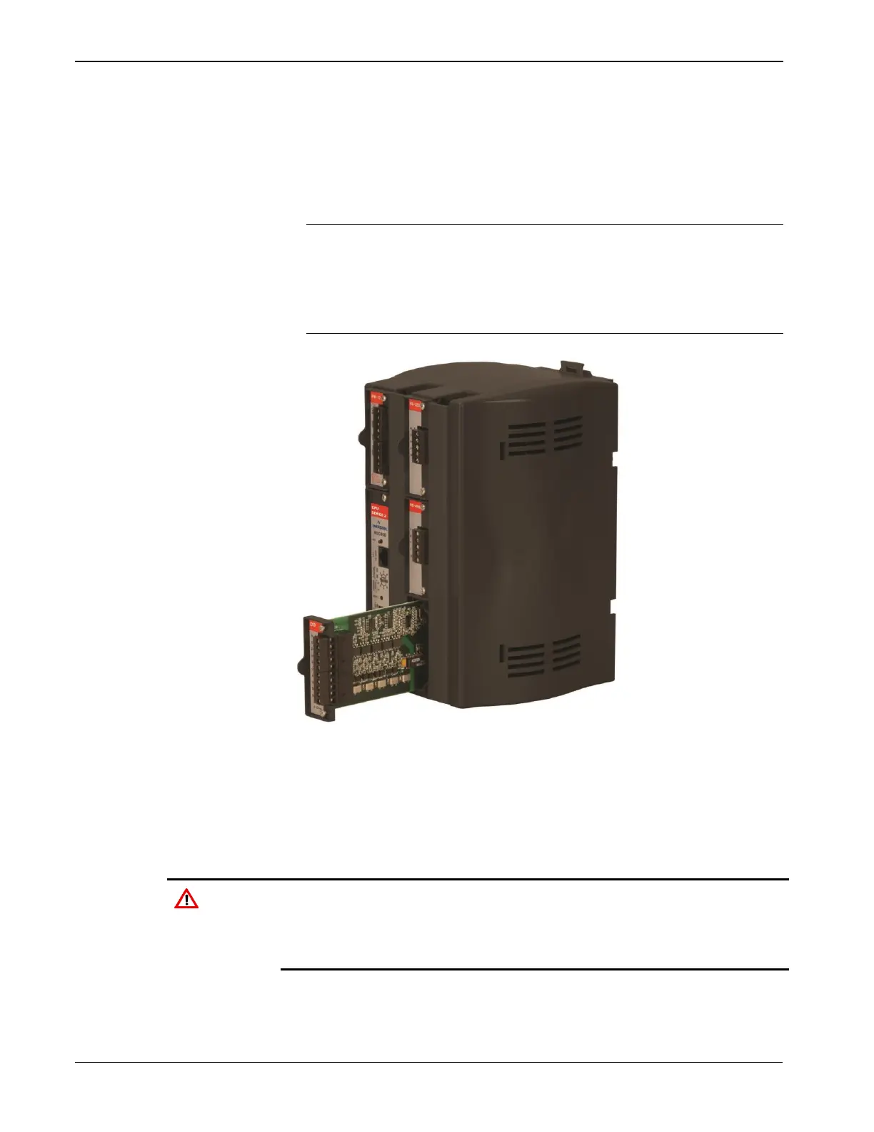
3. Insert the new I/O module through the module slot on the front of
the ROC800 or EXP housing. Make sure the label on the front of the
module faces right side up (refer to Figure 4-3). Gently slide the
module in place until it contacts properly with the connectors on the
backplane.
Note: If the module stops and will not go any further, do not force
the module. Remove the module and see if the pins are bent.
If the pins are bent, gently straighten the pins and re-insert
the module. The back of the module must connect fully with
the connectors on the backplane.
Figure 4-3. Installing an I/O Module
4. Tighten the captive screws on the front of the module.
5. Wire the I/O module (refer to Wiring I/O Modules).
6. Replace the wire channel cover.
Never connect the sheath surrounding shielded wiring to a signal
ground terminal or to the common terminal of an I/O module. Doing so
makes the I/O module susceptible to static discharge, which can
permanently damage the module. Connect the shielded wiring sheath
only to a suitable earth ground.
7. Connect to ROCLINK 800 software and login. The I/O modules are
self-identifying after re-connecting to ROCLINK 800 software.
8. Configure the I/O point.