EasyManuals Logo

Emerson ROC827 User Manual

Emerson ROC827
184 pages
To Next Page IconTo Next Page
To Previous Page IconTo Previous Page
Page #94 background imageLoading...
Page #94 background image
ROC800-Series Instruction Manual
4-8 Input/Output Modules Revised July-2017
D301250X012) or the ROCLINK 800 Configuration Software User
Manual (for ROC800L) (part D301246X012).
Note: The AI-16 module provides 16-bit resolution and uses a 24-bit
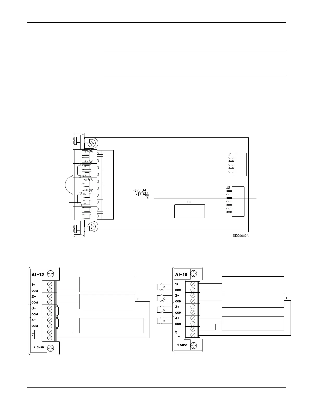
A/D converter. DIP switches on the AI-16 module (see Figure 4-
6) allow you to select between current and voltage loop input.
You can configure the AI (+T) module as either 12 or 24 Volt dc using
jumper J4 on the AI-12 module (see Figure 4-4). The AI modules can
provide isolated +12 Volt dc or +24 Volt dc field transmitter power on a
per-module basis. For example, one module can provide +12 Volts dc
for powering low power analog transmitters, while another module in
the same ROC800 can provide +24 Volts dc for powering conventional
420-mA transmitters. Refer to Figure 4-5.
A
12 / 24 V dc Jumper
Figure 4-4. AI-12 Jumper J4 (Shown Set to +12V)
1-5 VOLT DEVICE
EXTERNALLY POWERED
+
-
1-5 VOLT DEVICE
ROC800 POWERED
+
-
ROC800 POWERED
CURRENT LOOP DEVICE 4-20mA
-
+
OUT SIGNAL
COM IN
DOC0506C
+
+
+
OUT SIGNAL
COM
1-5 VOLT DEVICE
EXTERNALLY POWERED
1-5 VOLT DEVICE
ROC800 POWERED
CURRENT LOOP DEVICE 4-20mA
ROC800 POWERED
-
-
-
IN
DOC0514B
250
250
250
250
Figure 4-5. Analog Input Module Field Wiring (AI-12 and AI-16)
Precision
Resistor
A

Table of Contents

Questions and Answers:

Question and Answer IconNeed help?

Do you have a question about the Emerson ROC827 and is the answer not in the manual?

Emerson ROC827 Specifications

General IconGeneral
BrandEmerson
ModelROC827
CategoryController
LanguageEnglish

Related product manuals