14
Reference Manual
00809-0100-4021, Rev GC
Section 2: Installation
April 2014
Installation
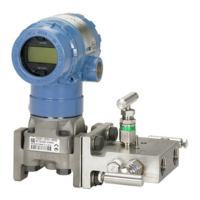
Figure 2-3. Incorrect Conduit installation
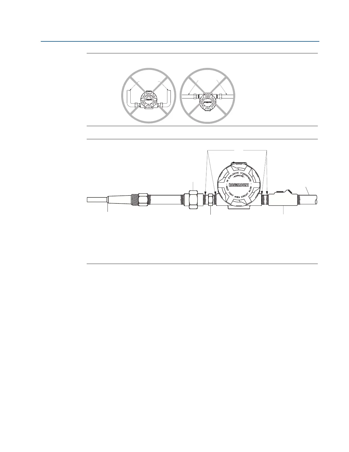
Figure 2-4. Recommended Mounting with Drain Seal
A. Sealing compound
B. Union coupling with extension
C. Conduit for field wiring
D. Thermowell
E. Sensor hex
F. Poured conduit seal (where required)
If mounting the transmitter directly to the sensor assembly, use the process shown in
Figure 2-5. If mounting the transmitter apart from the sensor assembly, use conduit between
the sensor and transmitter. The transmitter accepts male conduit fittings with
1
/2–14 NPT,
M20 × 1.5 (CM 20), PG 13.5 (PG 11), or JIS G
1
/2 threads (M20 × 1.5 (CM 20), PG 13.5 (PG 11), or
JIS G
1
/2 threads are provided by an adapter). Make sure only qualified personnel perform the
installation.
The transmitter may require supplementary support under high-vibration conditions,
particularly if used with extensive thermowell lagging or long extension fittings. Pipe-stand
mounting, using one of the optional mounting brackets, is recommended for use in
high-vibration conditions.
Conduit
lines
Conduit
lines