©2020 EMS Ltd. All rights reserved Page 12 of 36 MK349-0001-99 (Issue 1) 22/10/2020 AJM
SKIP THIS STEP IF CONNECTING TO AN ADDRESSABLE FIRE SYSTEM.
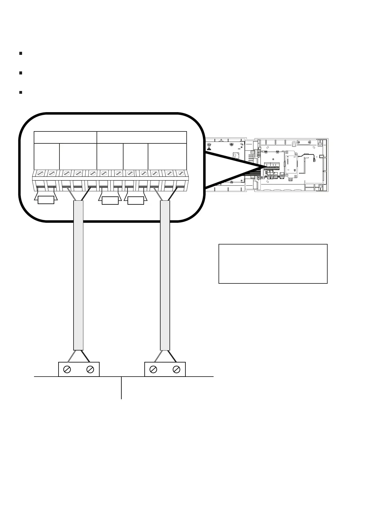
The WZM must be connected to a dedicated zone and sounder output.
The maximum cable length to connected devices is 10 m.
Conventional fire system wiring
FOOTNOTES
*
Ensure that the manufacturer’s specified end of line components and triggering
resistors are fitted. See the control panel’s instructions for more information.
BAT
ENABLE
TAMPER
RESET
AERIAL A AERIAL B
ATTENTION
ELECTROSTATIC
SENSITIVE DEVICE
RS232
EN54-4 UNIVERSAL PSU
SC-60-1000
INPUT: 220-240VAC, 50Hz, 0.3A
OUTPUT: 5.0-8.5VDC, 0.8A MAX
STATUS
FAULT
MAINS / CHARGER FAIL
BATTERY LOW
BATTERY FAIL
START
INPUT
L N
For additional information refer to TSD042
0359-CPR-00267
15
0905
SLIDE TO
REMOVE
EOL
(+) (-) (+) (+) (-) (+) (-) (+) (-) (+) (+) (-)
SOUNDER A
L1 L1 L2 EOL ALARM L1 L1 L2
IN OUT RES IN OUT
ZONE
A B
A B NC C NO NC C NO
FIRE
INPUT2
INPUT1
FAULT
FAULT
ACTIVE
FAULT
ACTIVE
A
B
C
D
R1 = Sounder circuit EOL
R2 = Zone circuit EOL
R3 = Alarm resistor
EOL
(+) (-) (+) (+) (-)
SOUNDER
ALARM
RES IN OUT
ZONE
L1 L1 L2
(+) (-) (+) (+) (-)
L1 L1 L2
EOL
(+) (-)
IN OUT
R3
R2
R1
ZONESOUNDER
+ -
Conventional fire system connections
+ -
*
*
*