Section C - Wiring
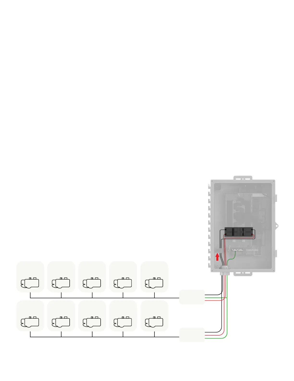
Wire the input from the PV
1. Use copper conductors sized to meet local code requirements
and voltage drop/rise considerations.
2. Bring in the wires from each AC branch circuit.
3. Connect the ground (green or green/yellow) to the ground bar.
4. Pass the L1 conductors from each PV branch circuit through
the Production CT in the same direction as the arrow on the
side of the CT.
5. Connect L1 and L2 (usually one black and one red) from each
AC branch circuit (PV and/or battery) to the circuit breaker(s).
Observe the L1 and L2 polarity marking at each breaker
position.
6. Torque all connections as indicated in the table on previous
page.
7. For IQ8 grid-forming installations (i.e., with an IQ System
Controller 3/3G), hold-down kits must be used for the
breakers for PV branch circuits as per the NEC code. The IQ
Combiner 5/5C SKU's (X-IQ-AM1-240-5-HDK and X-IQ-AM1-
240-5C-HDK) come pre-installed with the hold-down kit.
Junction Box
Junction Box
IQ6/7 or IQ8
Microinverter
IQ6/7 or IQ8
Microinverter
IQ6/7 or IQ8
Microinverter
IQ6/7 or IQ8
Microinverter
IQ6/7 or IQ8
Microinverter
IQ6/7 or IQ8
Microinverter
IQ6/7 or IQ8
Microinverter
IQ6/7 or IQ8
Microinverter
IQ6/7 or IQ8
Microinverter
IQ6/7 or IQ8
Microinverter
IQ Combiner 5/5C Quick Install Guide 22
 Loading...