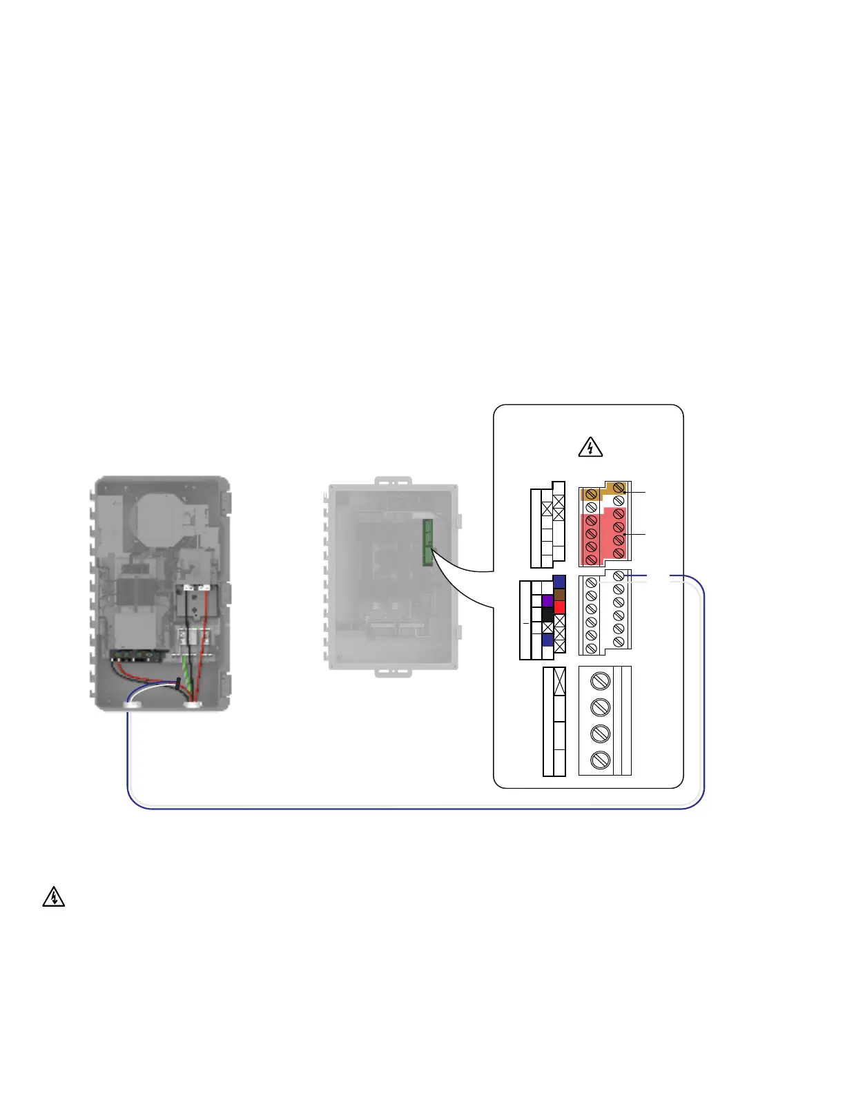
IQ Gateway Terminal Block
Not used Relay contacts
(if needed)
CU, C, AWG MIN
MEAS CAT III
OVC III
PD, B
OVC II
N L L
P
Digital Input
1 2 3 4 NO
REF CCommon
Relay
C C C
Production Consumption
Section D - Installing the current transformers
IQBattery 5P metering for
grid-forming systems
For grid-forming systems, IQBattery 5P needs to be installed in the
IQSystemController 3/3G.
The IQBattery CT needs to be installed on the L2 line of the IQBattery with the arrow
pointing towards the battery lugs in the IQSystemController.
Risk of electrocution and equipment damage! Do not install CTs when
current is owing in the sensed circuit. Always install CT wires in the
terminal blocks before energizing the sensed circuit.
Blue
White
IQ Combiner 5/5C Quick Install Guide37
 Loading...