Section D - Installing the current transformers
Consumption CT installation in
grid-tied systems (load with solar conguration)
Consumption CTs are installed on the service entrance when a site
requires to monitor the net import/export to the grid.
This is mandatory on sites where power export limiting (PEL)
restrictions must be met.
Make sure that the main load center wires are de-energized until you
have secured the CT wires in the terminal blocks.
Risk of electrocution and equipment damage! Do not install CTs when
current is owing in the sensed circuit. Always install CT wires in the
terminal blocks before energizing the sensed circuit.
IQ Gateway Terminal Block
Not used Relay contacts
(if needed)
CU, C, AWG MIN
MEAS CAT III
OVC III
PD, B
OVC II
NLL
P
Digital Input
1234 NO
REF CCommon
Relay
C C C
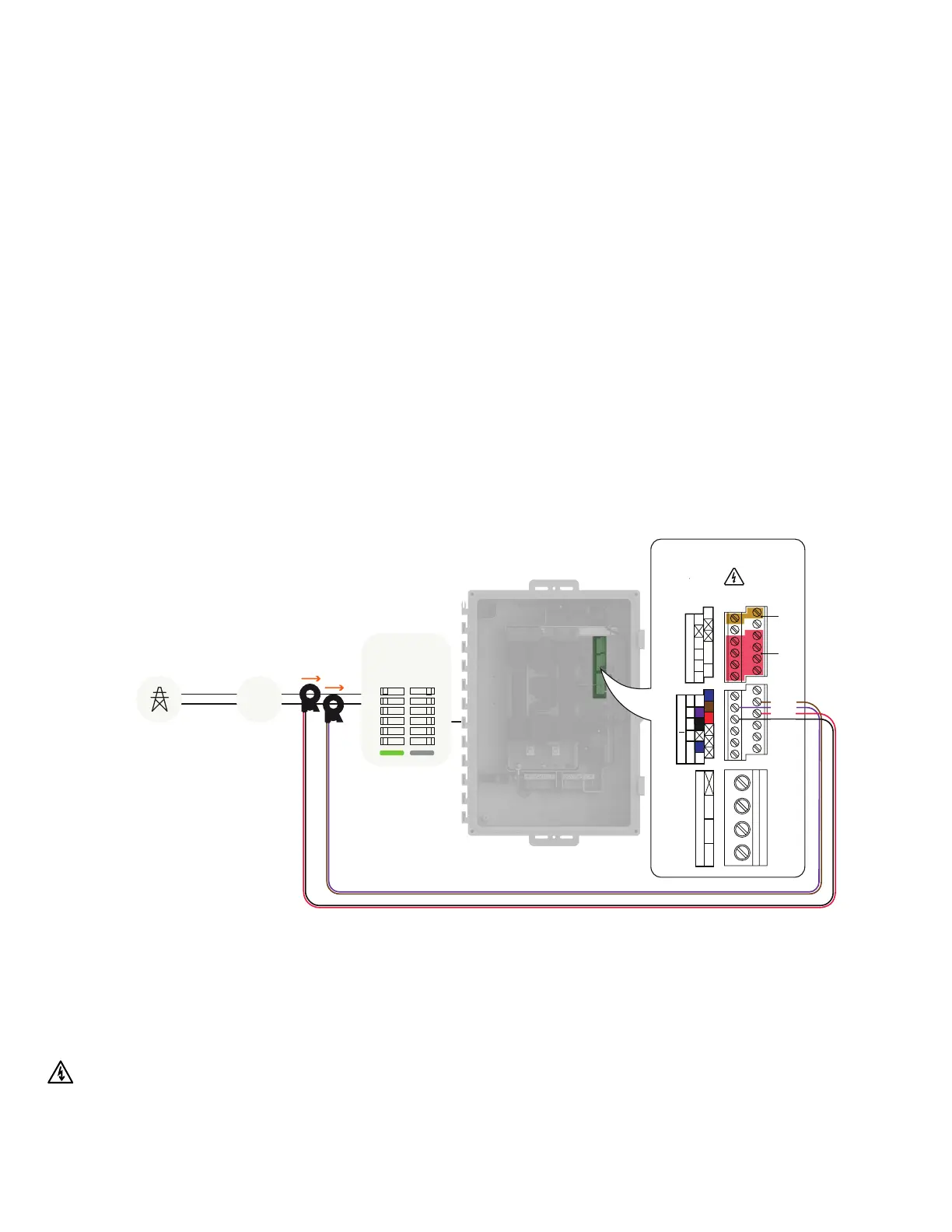
Grid Utility Meter
Wh
Main load
center
Production Consumption
Clamp the red and black C1 CT on the load center feed wire Line 1
(matching the IQGateway’s “L1” voltage terminal) with the CT arrow
pointing toward the load (away from the grid).
Clamp the purple and brown C2 CT on the load center feed wire
Line 2 (matching the IQGateway’s “L2” voltage terminal) with the
CT arrow pointing toward the load (away from the grid).
Tighten all connections using a 5 in-lbs torque.
Purple
Brown
Black
Red
IQ Combiner 5/5C Quick Install Guide33
 Loading...