Section D - Installing the current transformers
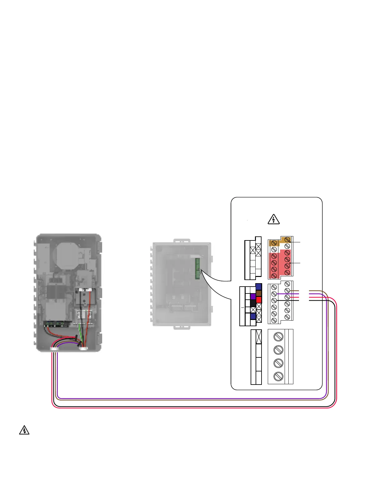
Consumption CT installation
in grid-forming systems
Consumption CTs are installed inside the IQSystemController3/3G
for grid-forming systems.
Clamp the red and black C1 CT on the load center feed wire Line 1
(matching the IQGateway’s “L1” voltage terminal) with the CT arrow
pointing toward the load (away from the grid).
Clamp the purple and brown C2 CT on the load center feed wire
Line 2 (matching the IQGateway’s “L2” voltage terminal) with the
CT arrow pointing toward the load (away from the grid).
Risk of electrocution and equipment damage! Do not install CTs when
current is owing in the sensed circuit. Always install CT wires in the
terminal blocks before energizing the sensed circuit.
IQ Gateway Terminal Block
Not used Relay contacts
(if needed)
CU, C, AWG MIN
MEAS CAT III
OVC III
PD, B
OVC II
N L L
P
Digital Input
1 2 3 4 NO
REF CCommon
Relay
C C C
Production Consumption
Purple
Brown
Black
Red
IQ Combiner 5/5C Quick Install Guide35
 Loading...