Section C - Wiring
Control (CTRL) wiring
between system components
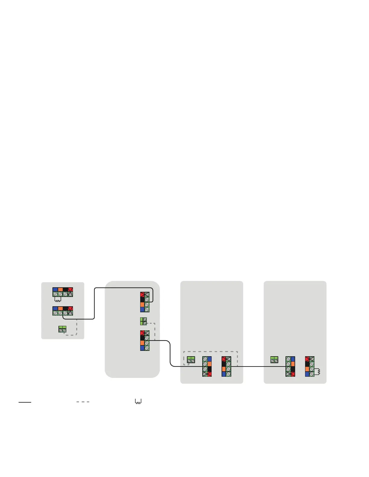
Control wiring guidance for the Enphase Energy System:
Refer to the following wiring sequences to understand the position
of the header with termination resistor, wiring order, and drain wire
termination location.
NOTE: The cumulative length of CTRL wiring across the system
cannot exceed 250 feet to ensure the system operates as per
specications.
NOTE: Ensure these guidelines are followed to avoid failures during
system commissioning:
• One header with a termination resistor should be installed
on each component that is at the extreme end of the control
network.
• The drain wire should only be terminated on one end of the
control wiring between system components.
IQCombiner5/5C
IQSystemController 3/3G
IQBattery 5P IQBattery 5P
21 3
4
21 3
4
21 3
4
21 3 4
21 3 421 3 4
21 3
4
21 3 4
Drain wireCTRL cable Termination resistor
• It is recommended that the drain wire be terminated at the
component from which control wiring for the section is
initiated.
• The same conduits can be used for power and control wire
routing only when using an Enphase CTRL cable, i.e., CTRL-
SC3-NA-01.
Sequence 1a:
IQCombiner5/5C → IQSystemController3G → IQBattery(s)5P
IQ Combiner 5/5C Quick Install Guide 28
 Loading...