Section C - Wiring
The table below provides the termination resistor locations for the
above sequences:
CONTROL WIRING SEQUENCE TERMINATION RESISTOR LOCATIONS
IQCombiner5/5C→IQSystemController3G→IQBattery(s)5P
1.IQCombiner5/5C
2. Last IQBattery5P in the daisy chain
IQCombiner5/5C→IQBattery(s) 5P → IQSystemController3/3G
1.IQCombiner5/5C
2.IQSystemController3/3G
IQSystemController3/3G → IQCombiner5/5C →IQBattery(s)5P
1.IQSystemController3/3G
2. Last IQBattery5P in the daisy chain
IQCombiner5/5C→IQBattery(s)5P
1. IQCombiner5/5C
2. Last IQBattery5P in the daisy chain
Drain wireCTRL cable Termination resistor
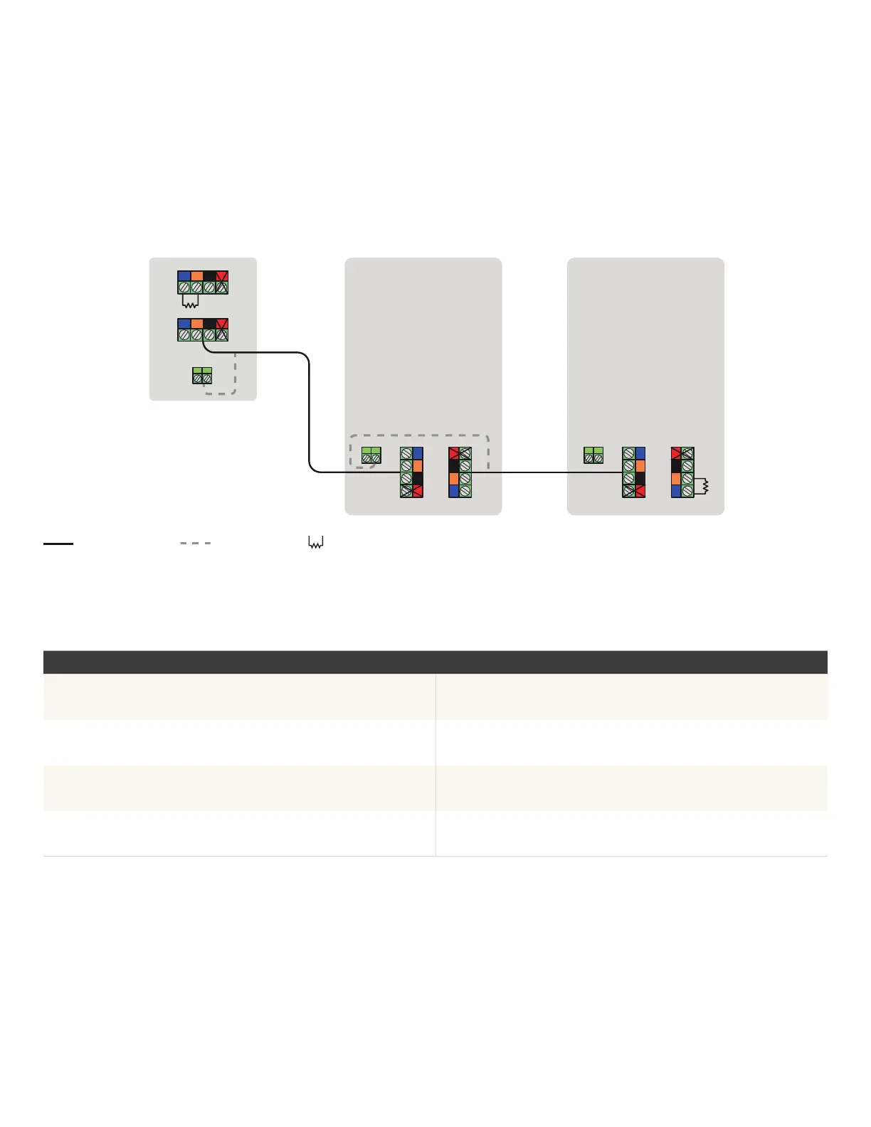
Sequence 4:
IQCombiner5/5C → IQBattery(s) 5P
21 3
4
21 3
4
21 3 4
21 3
4
21 3 4
21 3
4
IQ Combiner 5/5C IQ Battery 5P IQ Battery 5P
IQ Combiner 5/5C Quick Install Guide31
 Loading...