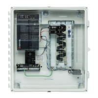
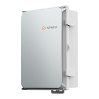
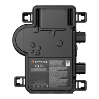
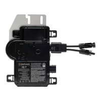
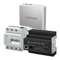
PRODUCT SKU
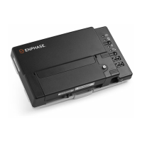
IQSystemController 3/3G SC200D111C240US01, SC200G111C240US01
IQCombiner5/5C
X-IQ-AM1-240-5 or X-IQ-AM1-240-5C or
X-IQ-AM1-240-5-HDK or X-IQ-AM1-240-5C-HDK
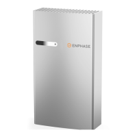
IQBattery 5P IQBATTERY-5P-1P-NA
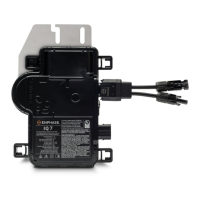
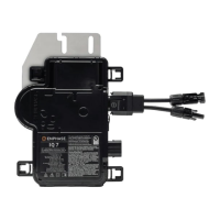
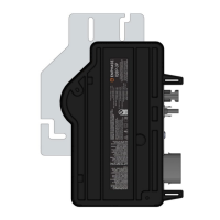
Microinverters IQ8 Series
1. Ensure availability of the following Enphase products, as
required, on-site to implement EPC:
2. Installation of the CTs
Based on the type of system (grid-forming or grid-tied) and the EPC feature being
enabled, the CTs may have to be installed in dierent locations on a site.
Section F - Operation
Setting up Enphase Power Control
on-site during commissioning
IQ Combiner 5/5C Quick Install Guide 44
NOTE: If the installer wants generator integration or if the
Main Panel Upgrade avoidance feature (applicable in partial
home back congurations and grid-tied PV only systems) is
enabled, the Consumption CTs need to be installed between the
IQSystemController3/3G and the main panel in order to monitor
and control the current back-fed from the IQSystemController to
the main panel. Installing the CTs at this location would impact the
Aggregate power export limiting (PEL) feature. For further details
refer CT Installation Guidelines Tech Brief.
CT TYPE QUANTITY LOCATION CONDUCTOR MEASURED DIRECTION OF ARROW
Consumption CT 2 IQSystemController
Conductor from the mains breaker to
the main panel or the utility meter
Towards the mains breaker inside
the IQSystemController 3/3G
Production CT* 1 IQCombiner5/5C L1 of all PV branch circuits
Away from the PV (towards the PV
breakers in the IQCombiner5/5C)
IQBattery CT 1 IQSystemController L2 of IQ Battery branch
Away from the IQBattery (towards the
battery lugs on the IQSystemController)
* IQCombiner5/5C has the production pre-wired in the box.

 Loading...

