Section 9: Standard & Optional Machine
Features
154
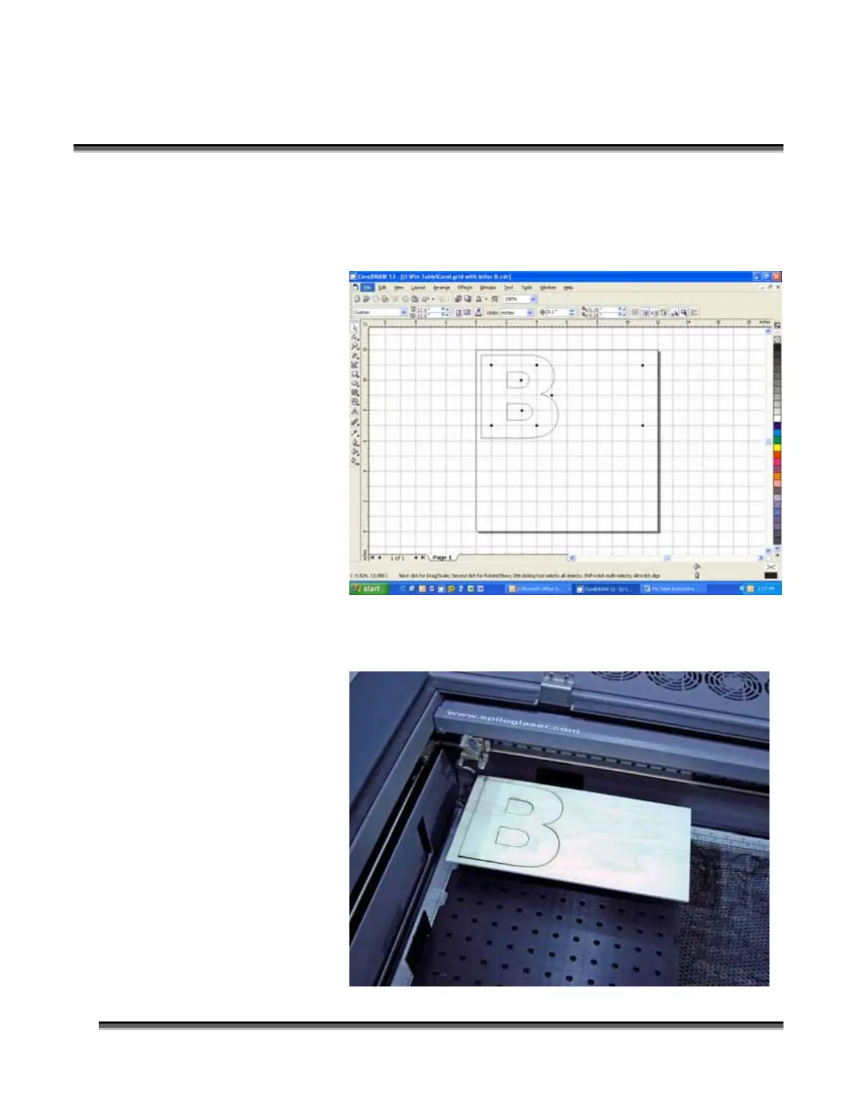
Set up your artwork on the grid so that the vector lines do not cross the path of any of
the pins. The small black circles within the letter “B” show the location of the pins.
Notice that you do not need to place pins in every available space, they just need to be
placed where they will support the work piece. For this piece we have also supported
the middle of the
“B” to show how to
support the waste
pieces if you do not
want them to fall
out after cutting.
The circles outside
of the “B” are to
support the long
piece of wood that
we are going to use
for cutting.
The next photo shows the Pin Table in the machine with the letter “B” cut out and
resting on the pins.
 Loading...