Section 9: Standard & Optional Machine
Features
150
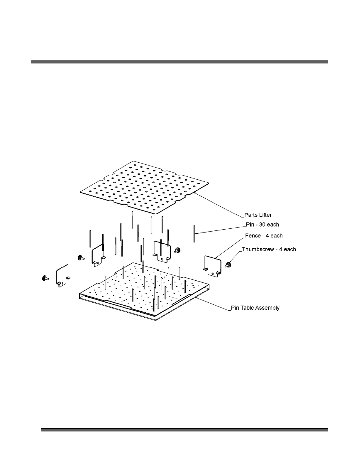
Pin Table
The Pin Table option offers a method for users to keep all back reflections of the laser
beam from marking the sides or back of the material being cut. The Pin Table lifts
the cutting material completely off the vector grid and provides a means to eliminate
the tick marks that can be created when the laser beam comes into contact with the
grid material.
The Pin Table is a 12” x 12” (305 x 305 mm) anodized aluminum table that holds
moveable support pins that can be placed anywhere on the table’s one inch (25.4 mm)
grid pattern. The moveable support pins allow the user to place the pins anywhere on
the grid in such a way that they support the material being cut while avoiding the
cutting path of the laser. This method of supporting the material produces cut edges
that do not have any marks from laser reflections. By setting up a grid pattern in your
graphics package to match the grid pattern of the Pin Table, you can easily ensure that
your cutting path will not contact the support pins.
 Loading...