Epson Artisan 800/Epson Stylus Photo PX800FW/TX800FW/Epson Artisan 700/Epson Stylus Photo PX700W/TX700W Revision C
DISASSEMBLY/ASSEMBLY Disassembly/reassembly procedures specific to Artisan 700/PX700W/TX700W 197
Confidential
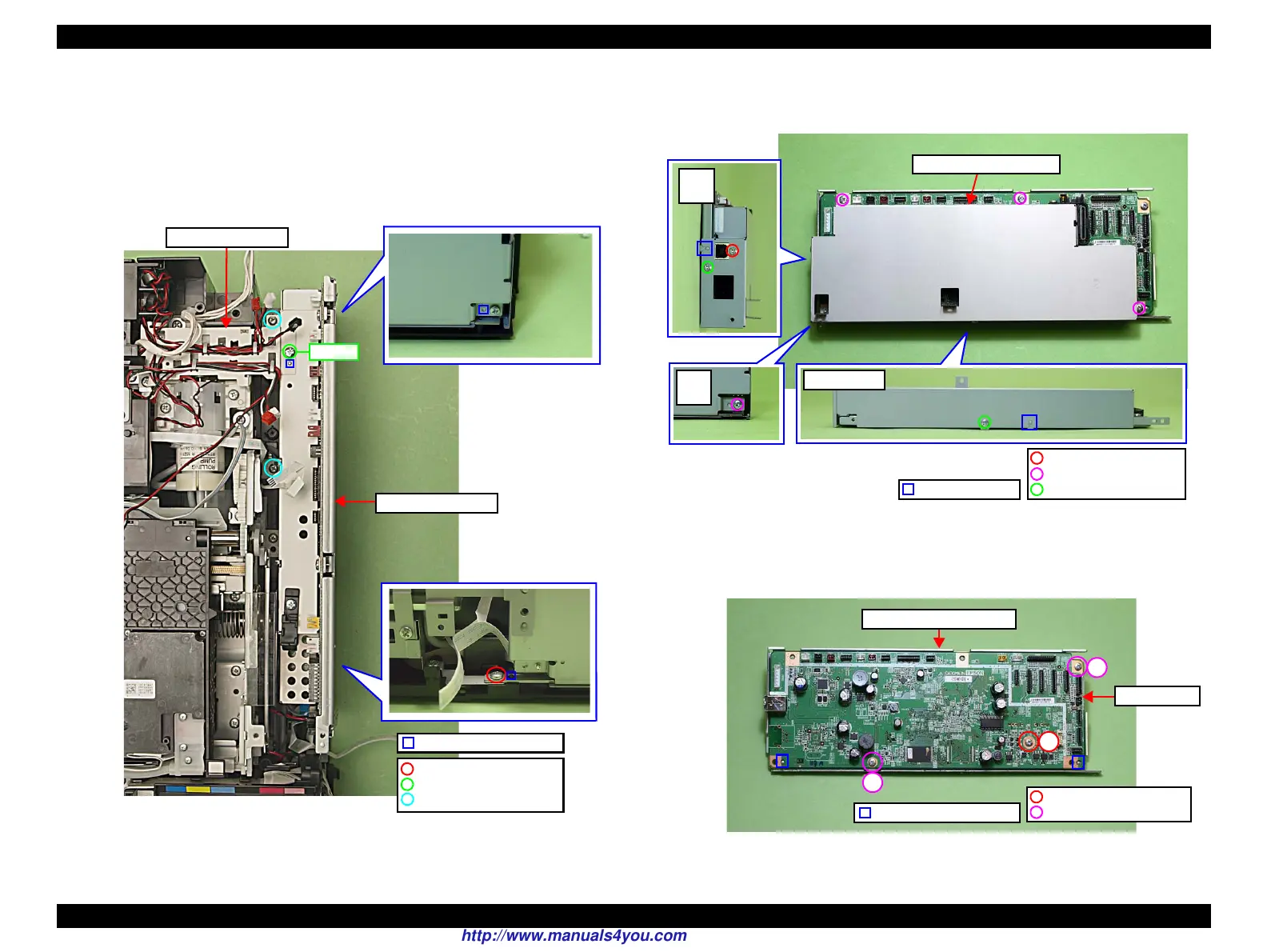
4. Disconnect the cables and FFCs connected to the section B of the Main
Board. (See
Fig. 4-229.)
5. Remove the screw (x1) that secures the Right Cable Frame and the Main
Board. (See
Fig. 4-229.)
6. Remove the screws (x3) that secure the Main Board Unit and remove the
Main Board Unit.
Figure 4-232. Removing the Main Board (1)
7. Remove the screws (x6) that secure the Upper Shield Plate M/B and remove
the Upper Shield Plate M/B.
Figure 4-233. Removing the Main Board (2)
8. Remove the screws (x3) that secure the Main Board, and remove the Lower
Shield Plate M/B from the Main Board.
Figure 4-234. Removing the Main Board (3)
Step 5
C.B.P. 3x10 (6±1Kgfcm)
C.B.S. 3x6 (7±1Kgfcm)
C.B.P. 3x8 (6±1Kgfcm)
Positioning hole & dowel
Main Board Unit
Right Cable Frame
Upper Shield Plate M/B
Dowel & groove
C.B.S. 3x6 (8±1Kgfcm)
C.B.S. 3x6 (4±1Kgfcm)
C.P. 3x6 (4±1Kgfcm)
1
2
3
C.B.S. 3x6 (8±1Kgfcm)
C.B.S. 3x10 (8±1Kgfcm)
Lower Shield Plate M/B
Main Board
Positioning hole & dowel
http://www.manuals4you.com

 Loading...


