Epson Artisan 800/Epson Stylus Photo PX800FW/TX800FW/Epson Artisan 700/Epson Stylus Photo PX700W/TX700W Revision C
DISASSEMBLY/ASSEMBLY Disassembly Procedures 135
Confidential
4.2.4.6 Ink System
Parts/Components need to be removed in advance:
ADF Unit (Artisan 800/PX800FW/TX800FW only)/Scanner Unit/Upper Left
Housing/Paper Guide Top Assy/Upper Housing
Removal procedure
1. Release the Carriage Lock and move the Carriage Unit to the center. (See
4.2.4.1 Printhead Step2 (p125).)
2. Remove the Waste Ink Tray Assy. (See 4.2.4.20 Waste Ink Tray Assy (p163).)
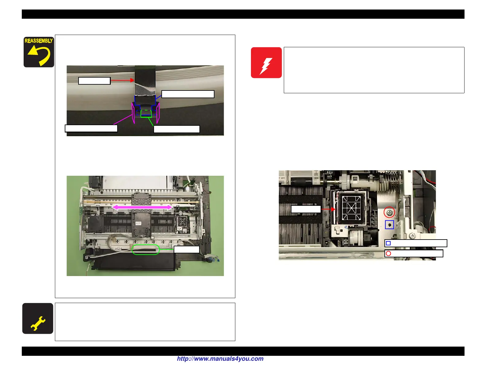
3. Remove the screw (x1) that secures the Ink System.
Figure 4-83. Removing the Ink System (1)
Secure the convex sections (x2) of the Clamp Tube into the hole
of it from outside to inside as shown in
Fig. 4-81.
Fold the wings inward as shown in Fig. 4-81.
Figure 4-81. Installing the Clamp Tube
When installing the Ink Supply IC Holder Assy, make sure to
remove slack around the section B by moving the Carriage Unit
between the 0-digit side and the 80-digit side a few times.
Figure 4-82. Installing the Ink Supply IC Holder Assy
For routing the FFCs, see 4.4 "Routing FFC/cables" (p202).
A D J U S T M E N T
R E Q U I R E D
After removing/replacing the Ink Supply IC Holder Assy, make the
specified adjustments. (See
Chapter 5 "ADJUSTMENT".)
Clamp Tube
Wings of Clamp Tube
Hole on Clamp Tube
Convex of Clamp Tube
When powering this product, high-voltage current may be applied
on the SUB Board. To prevent ELECTRIC SHOCK, do not touch
the SUB Board section when the power is ON.
If the shock should happen, the flowing current is very tiny, about a
few hundreds
μA, therefore it will not do any harm on the human
body.
C.B.P. 3x8 (6±1Kgfcm)
Positioning hole & dowel
Ink System
http://www.manuals4you.com

 Loading...


