REV.-A
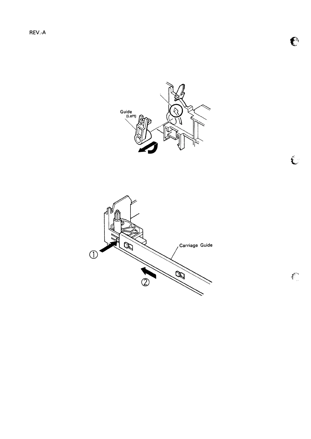
6. Turn the printer mechanism over so that it is again face up. Rotate the lever on the left side of the
carriage guide shaft counterclockwise, and pull it out through cutout A. Rotate the lever on the right
side of the guide shaft clockwise, and remove it in the same way.
Frame
A
o
Q
/
Carriage
Gu!de
Shaft Lever (Left)
%.
@
~
,)
1
\
P
Figure 4-29. Removal of Carriage Guide Shaft
7. Push the notch on the frame that is securing the carriage guide plate, and slide the plate to remove
it.
Plate
a
Figure 4-30. Removal of Carriage Guide Plate
c
..h
-1
,,,
. .
.
.A:
tin.’
..F,
-..
~
,,
8. Lift and remove the carriage unit, the carriage guide shaft, and the head adjust lever.
4-20

 Loading...


