REV.-A
2.1 OVERVIEW
This chapter describes the signals at the connectors linking the primary components of the LX-8 10/850.
These components include the printer mechanism and control circuits. The chapter also describes the
operation of the printer’s circuitry and
/printer mechanism.
2.1.1 Connector Summary
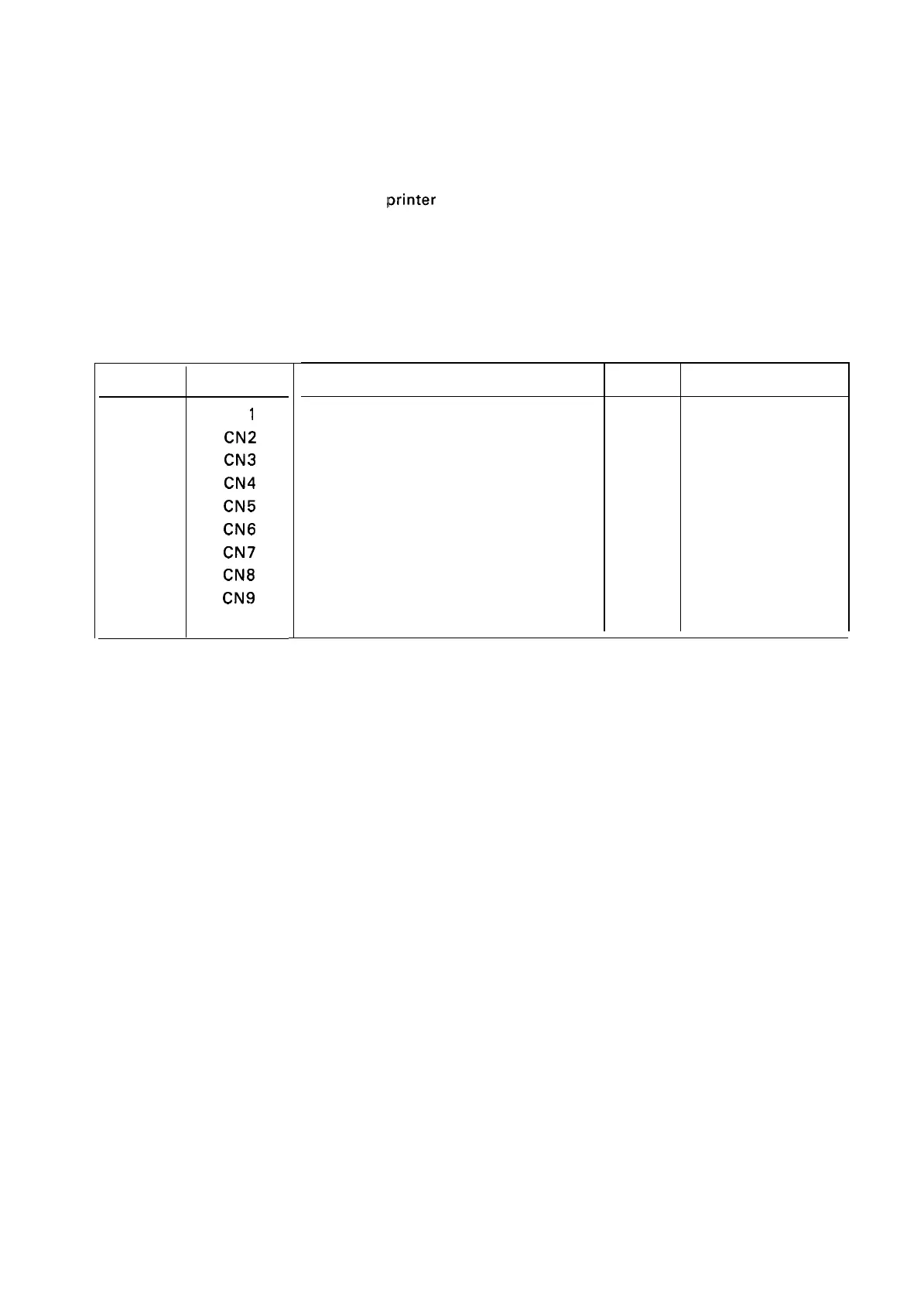
The interconnection of the primary components is illustrated in Figure 2-1. Table 2-1 summarizes the
functions, sizes, and types of the connectors shown in the figure.
Board
Connector
CN
1
CN2
CN3
CN4
CN5
TAMA
CN6
Board
CN7
CN8
CN9
CN 10
Table 2-’1. Board Connector Summary
Function
Pins
Reference Table
Host l/F (Parallel)
36 1-11
Optional I/F
:
Board
26 A-8
Control Panel
10
A-9
Release Lever
2
A-1 O
CR Motor and PF Motor
12
A-1 1
PE Signal
2
A-12
Home Position Signal
2 A-13
Head
12
A-1 4
AC Power Input
4
A-15
DC Power Input (OEM)
4
A-16
2-1

 Loading...


