REV.-A
1.3 INTERFACE OVERVIEW
The standard 8-bit parallel interface provided with this printer meets the specifications described below.
Data Format
8-bit parallel
Synchronization
By STROBE pulse
Handshaking
By BUSY and
ACKNLG signal
Signal Level
TTL-compatible
Adaptable Connector 57-30360 (amphanol) or equivalent
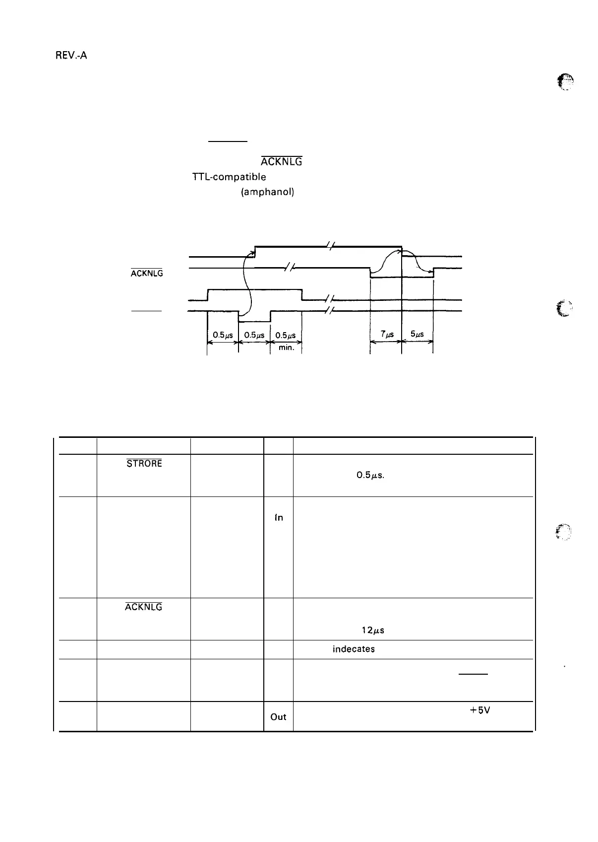
Data Transmission Timing See Figure 1-6
/[
BUSY
A
,
{ ,/,, .
ACKNLG
DATA
STROBE
o.5#s
min.
min.
Figure 1-6. Data Transmission Timing
Table 1-11 shows the connector pin assignments and signal functions of the 8-bit parallel interface.
Table 1-11. Connector Pin Assignments and Signal Functions
Pin No.
Signal Name
Return Pin No. DIR Functional Description
1
STRORE
19
In
Strobe pulse to read the input data. Pulse width must
be more than
0.5,us.
Input data is latched at falling edge
of this signal.
2
DATA 1
20
In
Parallel input data to the printer.
3
DATA 2
21
[n
“HIGH” level means data “ 1“.
4
DATA 3
22
In
“LOW” level means data “O”.
5
DATA 4
23
In
6
DATA 5 24
In
7
DATA 6 25
In
8
DATA 7
26
In
9
DATA 8
27
In
10
ACKNLG
28 out This pulse indicates data is received and ready to
accept next data.
Pulse width is
121.M
approx.
11
BUSY
29 out
“HIGH”
indecates
printer cannot accept next data.
12
PE
30 out
“HIGH” indicates paper-out.
This signal is effective only when ERROR signal is
“LOW”.
13
SLCT
out
Always
“HIGH” output. (Pulled up to
+5V
through
—
3.3kohms register.)
1-12

 Loading...


