REV.-A
Table 1-11. Connector Pin Assignments and Signal Functions (Cont.)
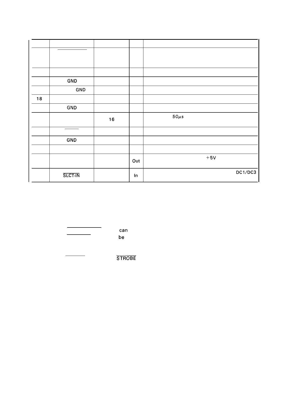
Pin No.
Signal Name Return Pin No.
DIR
Functional Description
14
AUTOFEED-XT
—
In
if “LOW” when the printer is initialized, a line
feed is
automatically performed by input of “CR” code. (Auto
LF)
15
Not used
16
GND
Ground for twisted-pair grounding
17
Chassis
GND
— —
Chassis ground level of printer
18
Not used
9 to 30
GND
Grounds for twisted-pair grounding
31 I NIT
Pulse (Width:
50#s
min., active “LOW”) input for printer
16
In
initialization.
32
ERROR out “LOW” indicates some error is occurred in the printer.
33
GND
—
—
Ground for twisted-pair grounding
34
—
—
Not
used
35
out Always “HIGH”. (Pulled up to
+5V
through 3.3 Kohms
—
register.)
36
SLCT-IN
In
If “LOW” when prinater is initialized, the DC1/DC3
—
control is disabled.
NOTES: 1. “DIR” refers to the direction of the signal flow as viewed from the printer.
2. “Return” denotes a twisted-pair return line.
3.
The cable used must be shielded to prevent noise.
4. All interface conditions are based on TTL levels. Both the rise and fall times of all signals
must be less than 0.2 us.
5. The AUTO FEED-XT signal
c:an
be set LOW by DIP switch 2-4.
6. The SELECT-IN signal can
ble
set LOW by jumper 1.
7. Printing tests, including interface circuit tests, can be performed without using external
equipment by setting DATA 1-8 of the interface connector to certain codes and connecting
the ACKNLG signal to the
STROBE signal.
1-13

 Loading...


