REV.-A
2.2.1.4
+5V
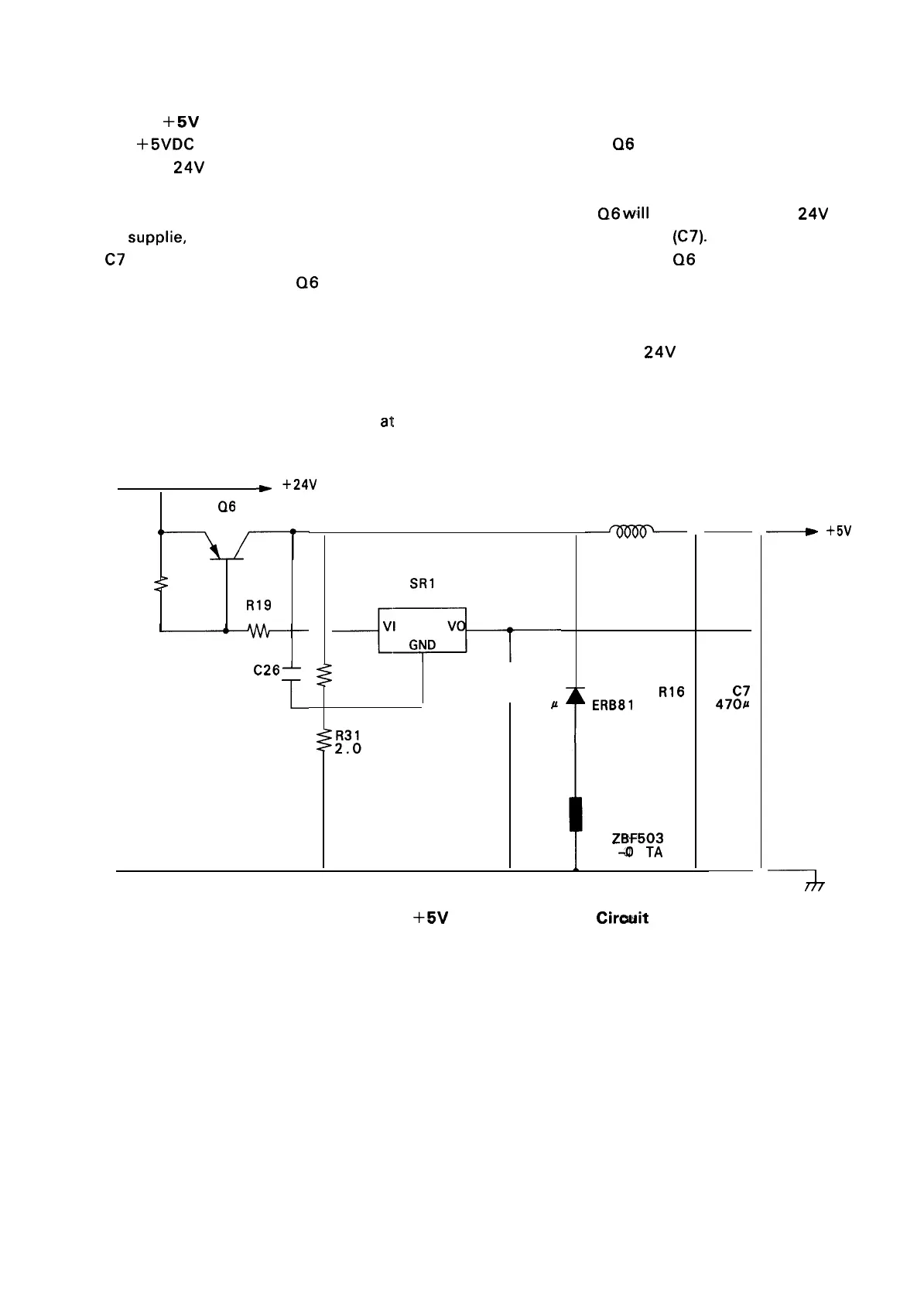
DC Power Supply Circuit
The
+5VDC
is generated by the switching and step-down action that Q6 applies to the 24VDC supplied
from the
24V
power circuit.
Immediately following power up,
VI of SR 1 will be LOW, so that
Q6
will
be ON. Therefore, +
24V
will
be
supplie, via Q6, to the chopper circuit (D2, L2) and the smoothing circuit (C7). When the charge in
C7 reaches 5V, however, SR 1 brings VI into a high-impedance condition, and
Q6
goes OFF. Thereafter,
based on this 5V charge,
Q6
will switch ON when the voltage drops, and switch off when the voltage
rises to a certain level. This intermittent action will generate a stable + 5V voltage.
The chopper circuit provided at the output stage acts, just as with the
24V
voltage, to stabilize the
current.
R31 serves to control the 5V output
at a slightly higher (about 5 mV) level, so as to prevent voltage
drop to due switching delay.
*
+24V
Q6
B1 151
R18
::
22<“
R19
82
C26~
470p
film
1
SR1
78L05A
+~’1
R37
2K
1
C27
-
-0.1
P
L2
LP201-2R550
D2
R16
ERB81
19.f[
-004
B2
Z13F503
-III 1
TA
C7
4701J
10V
~
+5V
+
7
—
Figure 2-2’1.
+5V
DC Power Supply
Circwit
2-19

 Loading...


