REV.-A
Chopping Circuit
c
.,
‘:!
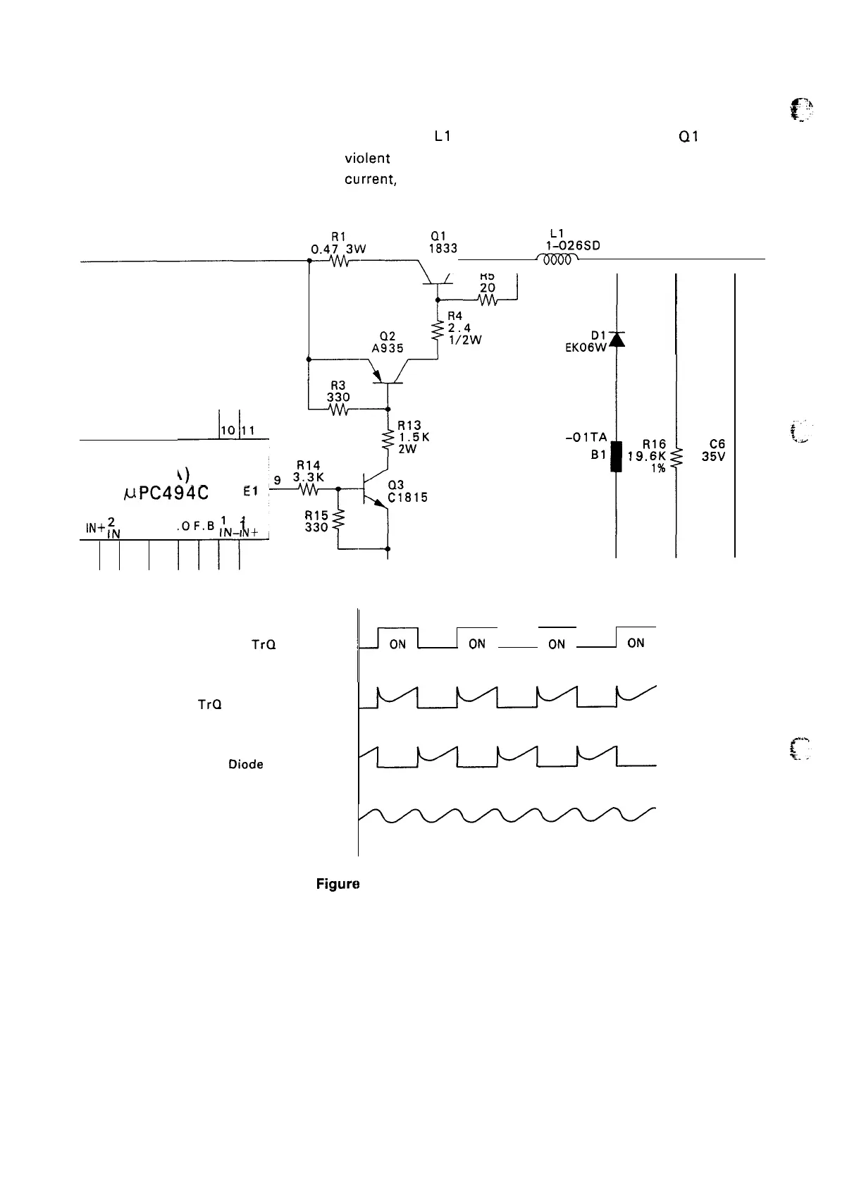
A chopper circuit consisting of diode D 1 and coil
L1
is utilized at the output stage. If
Q1
in ON, the
-,
coil acts as a resistor, and suppresses vic)lent current surges. When Q 1 goes OFF, the stored energy
in the coil generates a reverse starting
current, and current flows via D 1. Thus, the circuit works as a
current stabilizer.
0.4Y3VV
D
1:’33
LP40
l~!126SD
~~
4 .-
1
T
T
T
NCNC
K
3:30
1o11
,1::-
-Lr
R13
ZBF503
1.5K
-OITA
2W
El
(3A)
R14
93.3K
UPC494C
El
Q3
C1815
2
IN+
;N
D. T. CR. O F. B
1
1
R15
IN-IN+
330
1<
R16
19.
6K
3::
1%
2200/1
TrQ 1 Emitter
i
~
OFF
~~ OFF
ON
OFF
~fq
TrQ
1 Emitter Current
Oiode
D 1 Current
Current at chock
coil
——————————————-—-———————-
Figure
2-20. Chopping Circuit
2-18

 Loading...


