REV.-A
Switching Pulse Output
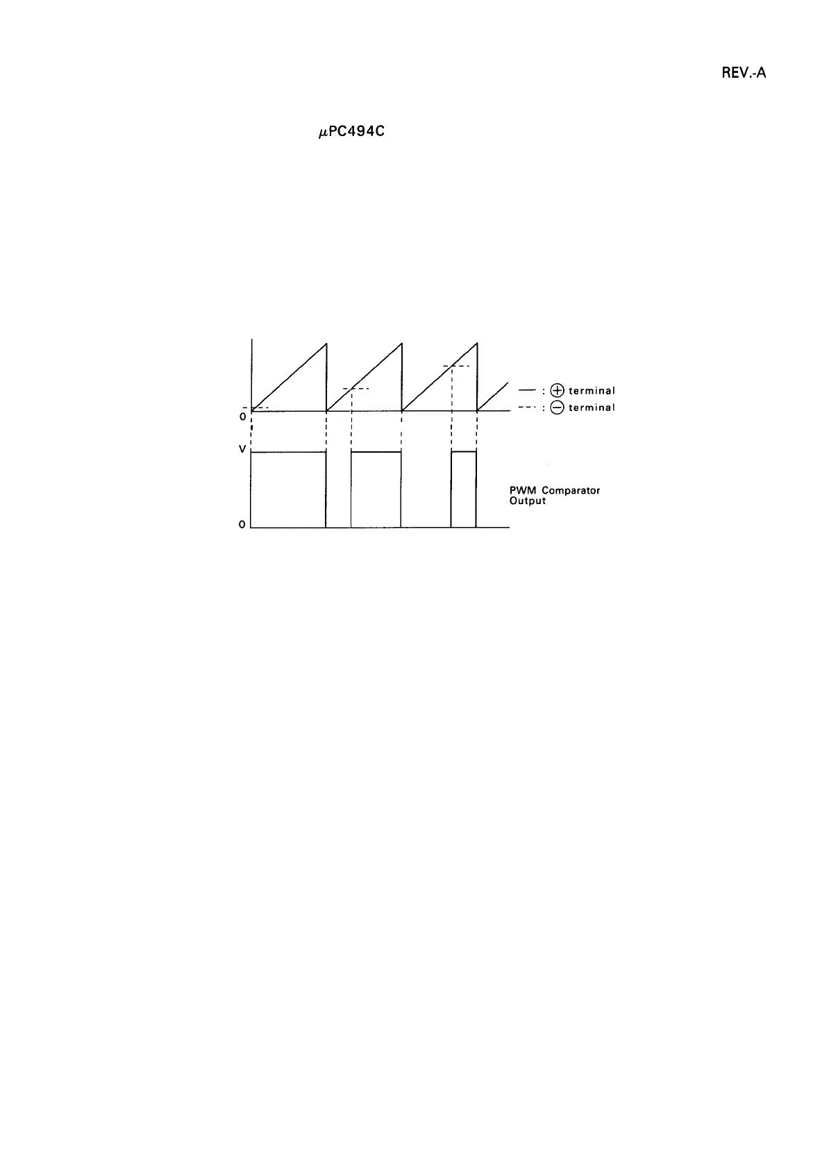
The output of the error amplifier in
KPC494C
is determined by the difference between the output pulse
of the internal oscillating circuit and the feedback voltage from the + 24V output. The feedback voltage
changes according to printer operation (i.e., printer load). The output of the error amplifier acts to
minimize this change, however, by responding as indicated in Figure 2-19.
Operation Low feedback voltage: Amplifier ON time increases (supply voltage increase)
High feedback voltage: Amplifier ON time decreases (supply voltage decreases)
v
I
1(
1
II
Im_IL’’’’ompara’or
Figure 2-19. output Transistor Drive Waveform
2-17

 Loading...


