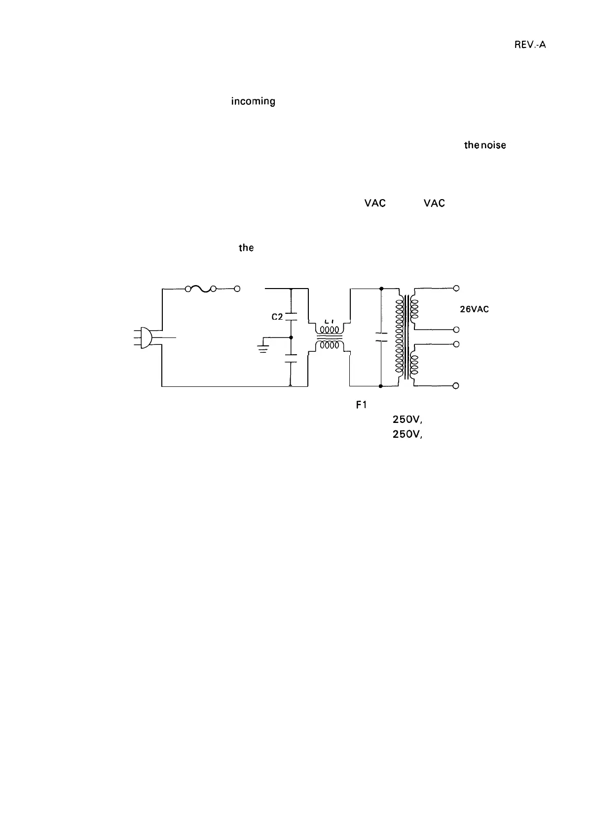
2.2.1.1 TA Filter Unit
The filter board and the transformer are integrated into a single unit. This unit also
power switch and the inlet for the
incolming AC cable.
REV.-A
incorporates the
The incoming AC power passes first through the over-current protection fuse (F 1 ) and the power switch,
and then into the filter circuit comprised of C 1, C2, C3, and L 1. This circuits removes
the
noise
on the
AC input line, and also serves to present noise generated within the printer from running through the
AC line.
The transformer steps down the incoming AC power into 26
VAC and 12 VAC outputs. To prevent
overheating, a temperature fuse is incorporated into the transformer.
Figure 2-12 illustrates the design of
the!
circuit.
AC
Power SW
FI -.
CN1
o
C2
red
26VAC
INPUT
-L
a=
‘
LI
C3
—
—
—
—
cl
blue 12VAC
F1
:
125V, 1.25A (120V Version)
250V,
0.63A (220V Version)
250V,
0.63A (240V Version)
Figure 2-12. Transformer Circuit
2-11
 Loading...