REV.-A
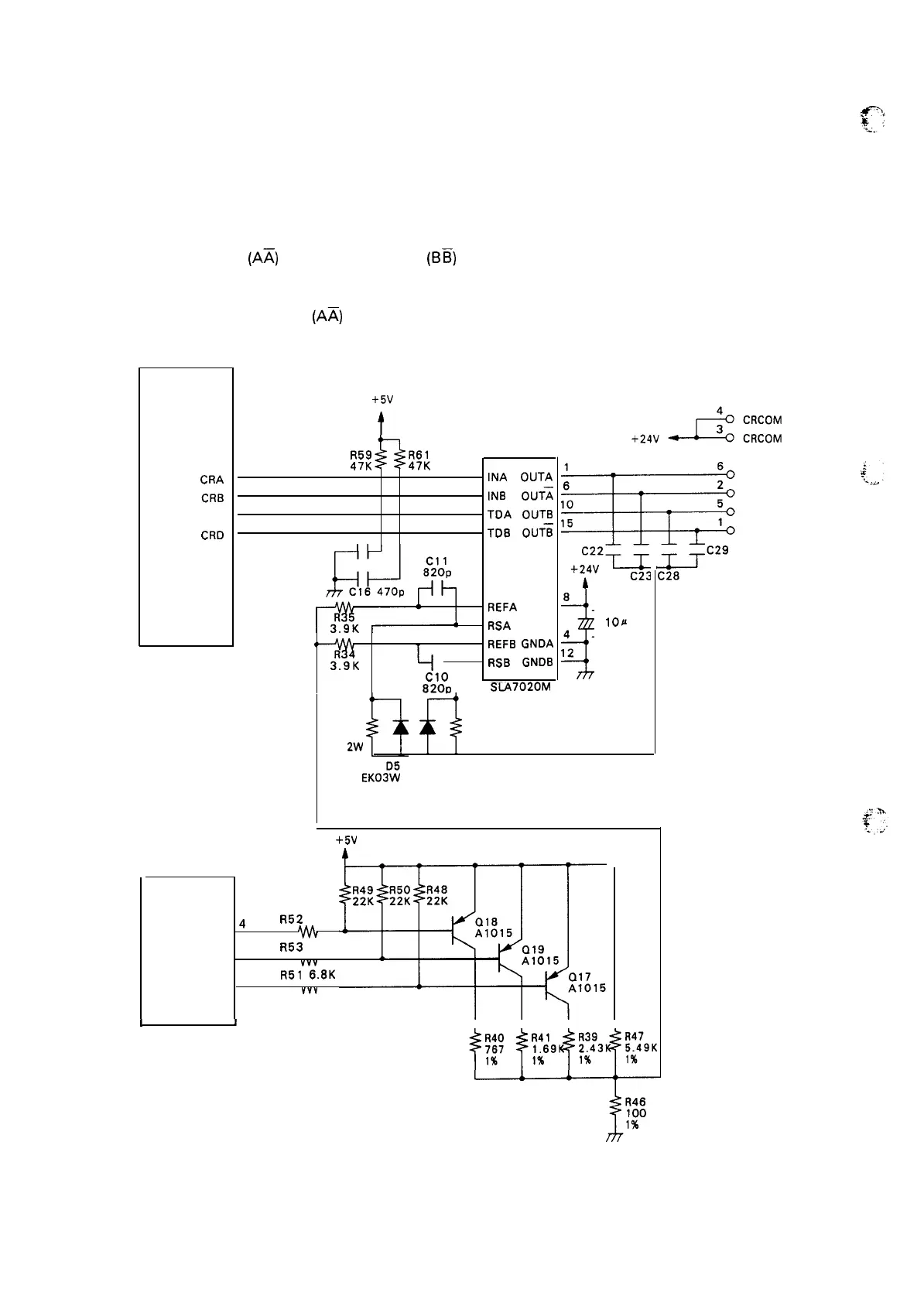
2.2.3.4 Carriage Motor Drive Circuit
This unit utilizes an SLA7020M IC for the step motor drive. This IC causes the motor to be driven at
the specified current. The IC utilizes a MOSFET power element, so that heat generation is low, and there
is no need to use a radiator board. The current value is determined by the value of the external voltage
input.
Within the IC, the AB
(Ax) phase and the CD
(BE)
phase are completely differentiated, and create
identical circuits.
For convenience, only the AB
(Ax) circuit is explained below. Figure 2-26 shows the carriage motor
drive circuit. Figure 2-27 shows the SLA7020M circuit diagram.
GA
E05A30
(3 B)
C~A
CRB
CRC
CRD
+5V
t
R59
R61
4
47K
47K
5
5
INA
OUTA
14
6
INB
OUT~
2
7
TDA
OUTB
11
cl 5 470p
TDB
OUTS
( 1A)
3
REFA
VS
7
RSA
13
4
REFB
GNDA
t-
9
RSB
GNDB
Clo
820v
SLA7020M
3
8
+ C25
10X
4
– 50V
12
R30
R29
1.0
1.0
2%
2W
2% 2W
EKOffi
I
D4
EK03W
G
P
470p 500V x4
+5V
A
CPU
!LPD78 10H G
4
R52
6.8K
( 2 C) PA3
5
R53
6.8K
PA4
Vvv
6
R51
6.8K
PA5
*VV
CR A
CR 8
CR C
CR D
I
t
I
I I I
T
Figure 2-26. Carriage Motor Drive Circuit
2-24

 Loading...


