REV.-A
2.2.6 Host Interface
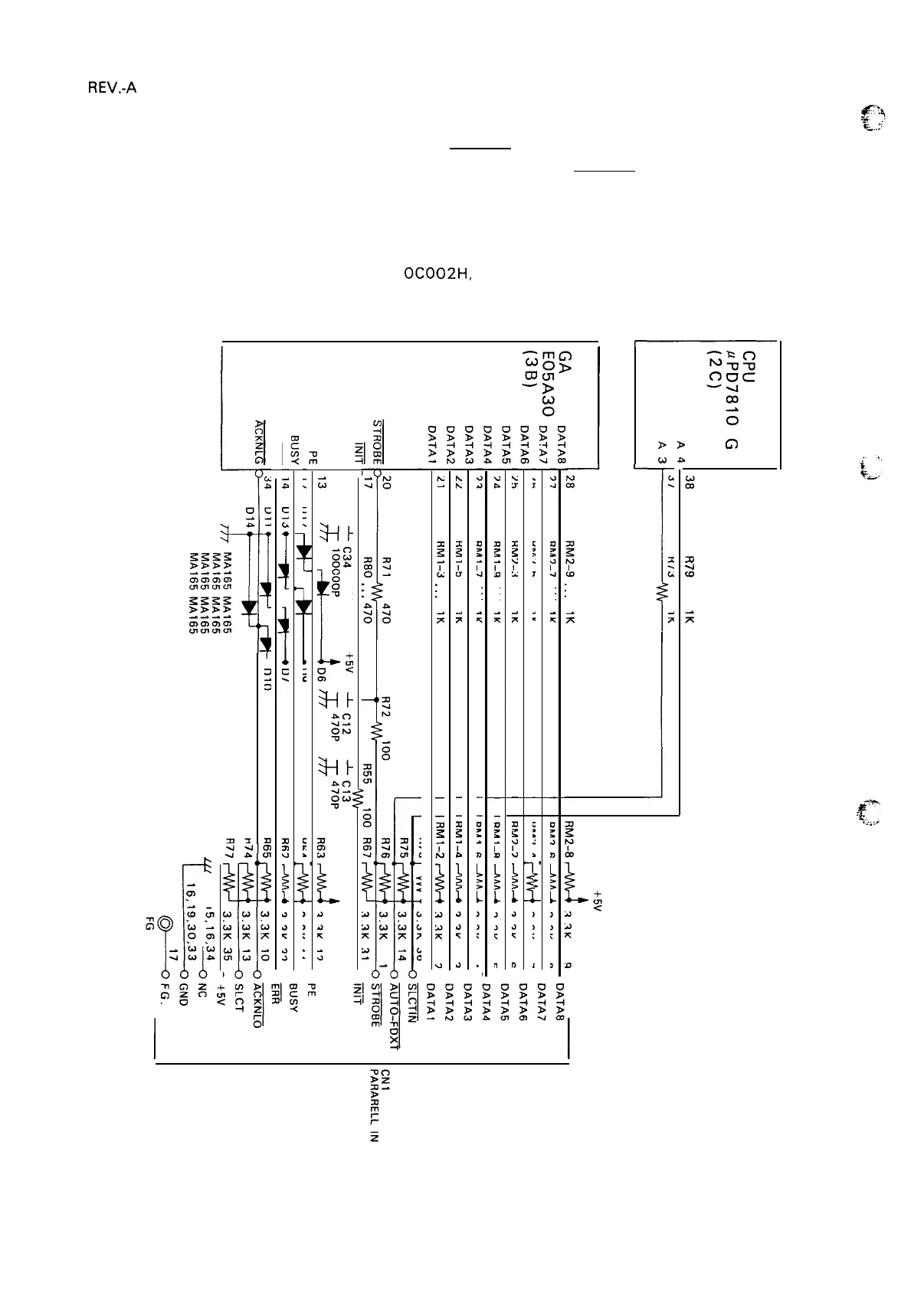
The host interface circuit is
shown in Figure 2-49. STROBE pulses from the host computer pass through
the low-pass filter, consisting of R72 and C 12, and flow into the STROBE terminal.
These pulses latch the parallel data and set the BUSY signal HIGH, so that subsequent data transfer
is inhibited.
At this time, the CPU, by reading address
OCO02H, can detect whether the data from the computer
are latched in
read the data.
the gate array. When the CPU determines that data have been latched, it proceeds
After the data have been read, the gate array automatically resets its busy signal.
to
s
x
>>
c1
Zz
(A)a
xl
.4
w
L
-1
$?
-!:.,:;
T
0)
--
Figure 2-49, Host Interface
2-44

 Loading...


