EasyManua.ls Logo

Epson RC700-A - Pin Assignments

Epson RC700-A
228 pages
Print Icon
To Next Page IconTo Next Page
To Previous Page IconTo Previous Page
Loading...
Functions 13. I/O Connector
150 RC700 Series Rev.3
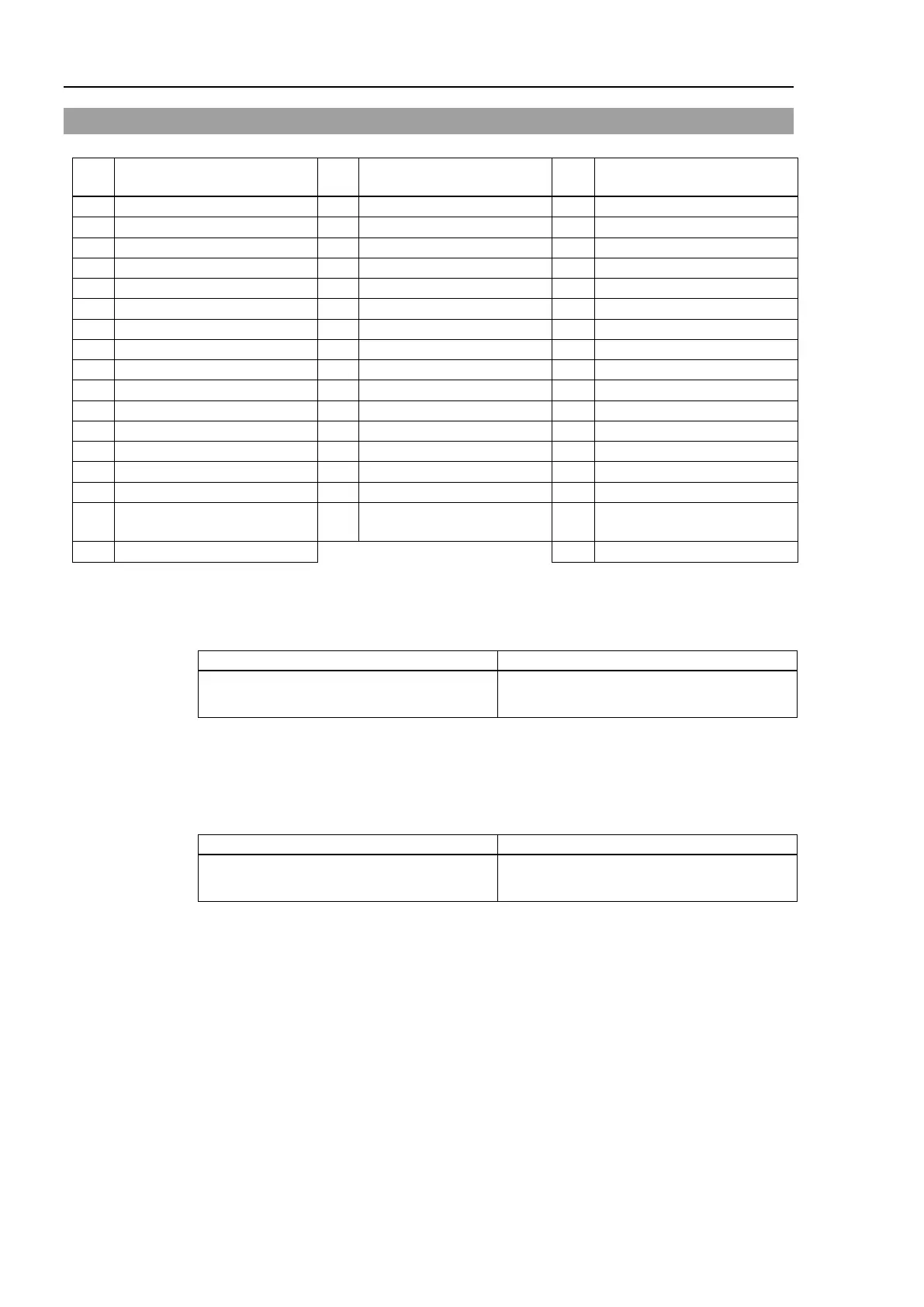
13.3 Pin Assignments
Pin
No.
Signal Name
Pin
No.
Signal Name
Pin
No.
Signal Name
1
Input common No. 0 to 7
18
Input common No. 8 to 15
34
Input common No. 16 to 23
2
Input No. 0 (Start)
19
Input No. 8
35
Input No. 16
3
Input No. 1 (SelProg1)
20
Input No. 9
36
Input No. 17
4
Input No. 2 (SelProg2)
21
Input No. 10
37
Input No. 18
5
Input No. 3 (SelProg4)
22
Input No. 11
38
Input No. 19
6
Input No. 4 (Stop)
23
Input No. 12
39
Input No. 20
7
Input No. 5 (Pause)
24
Input No. 13
40
Input No. 21
8
Input No. 6 (Continue)
25
Input No. 14
41
Input No. 22
9
Input No. 7 (Reset)
26
Input No. 15
42
Input No. 23
10
Output No. 0 (Ready)
27
Output No. 6 (SError)
43
Output No.11
11
Output No. 1 (Running)
28
Output No. 7 (Warning)
44
Output No.12
12
Output No. 2 (Paused)
29
Output No. 8 (EstopOff)
45
Output No.13
13
Output No. 3 (Error)
30
Output No. 9
46
Output No.14
14
Output No. 4
31
Output No.10
47
Output No.15
15
Output No. 5 (SafeguardOn)
32
Not Used
48
Not Used
16
Not Used
33
Output common No. 8 to
15
49
Not Used
17
Output common No. 0 to 7
50
Not Used
The remote function inside ( ) in the table above is initially assigned to the input 0 to 7 and
output 0 to 8.
For further details, refer to 14. I/O Remote Settings.
Controller:
Connector
Standard
I/O Connector (Controller side)
D-sub 50 male pin
Screwlock #4 - 40
* The I/O connector, I/O cable, and terminal block are offered as options.
* I/O connector is included with shipment.
Drive Unit:
Connector
Standard
I/O Connector (Drive Unit side)
D-sub 50 male pin
Screwlock #4 - 40
* The I/O connector, I/O connector cable, terminal block, and I/O connector kit are offered
as options.

Table of Contents

Other manuals for Epson RC700-A

Related product manuals