Installation 2. Installation
RC700 Series Rev.3 37
2.6.10 Resetting the Safeguard
Ensure that the robot system can only be restarted through careful operation from outside
the safeguarded system. The robot will never restart simply by resetting the safeguard
interlock switch. Apply this concept to the interlock gates and presence sensing devices for
the entire system.
2.6.11 Robot Operation Panel
The robot operation panel must not be located inside of the robot work envelope / work
cell. Ensure that the robot system can be operated from outside of the safeguard.
2.7 Connecting
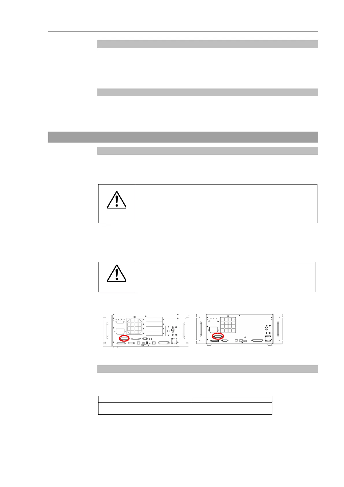
2.7.1 Connection to EMERGENCY Connector
The details of safety requirements for this section are described in Safety Manual. Please
refer to them to keep the robot system safe.
WARNING
Not only when turning ON the device, but also changing use
environment such as add options or
replace parts for
maintenance, make sure that the emergency stop or safety
door work properly.
Connect a safeguard switch or Emergency Stop switch to the Control unit and Drive unit
EMERGENCY connector for safety.
When nothing is connected to the EMERGENCY connector, Control unit and Drive unit
does not operate normally.
WARNING
Before connecting the connector, make sure
that the pins are
not bent. Connecting with
the pins bent may damage the
connector and result in malfunction of
the robot system.
Safety Door Switch and Latch Release Switch
The EMERGENCY connector has input terminals for the Safety Door switch and the
Em
ergency Stop switch. Be sure to use these input terminals to keep the system safe.
EMERGENCY connector
(Controller side)
D-sub25 Pin (male)
Screwlock #4-40
 Loading...


