Functions 16. Option Slots
RC700 Series Rev.3 167
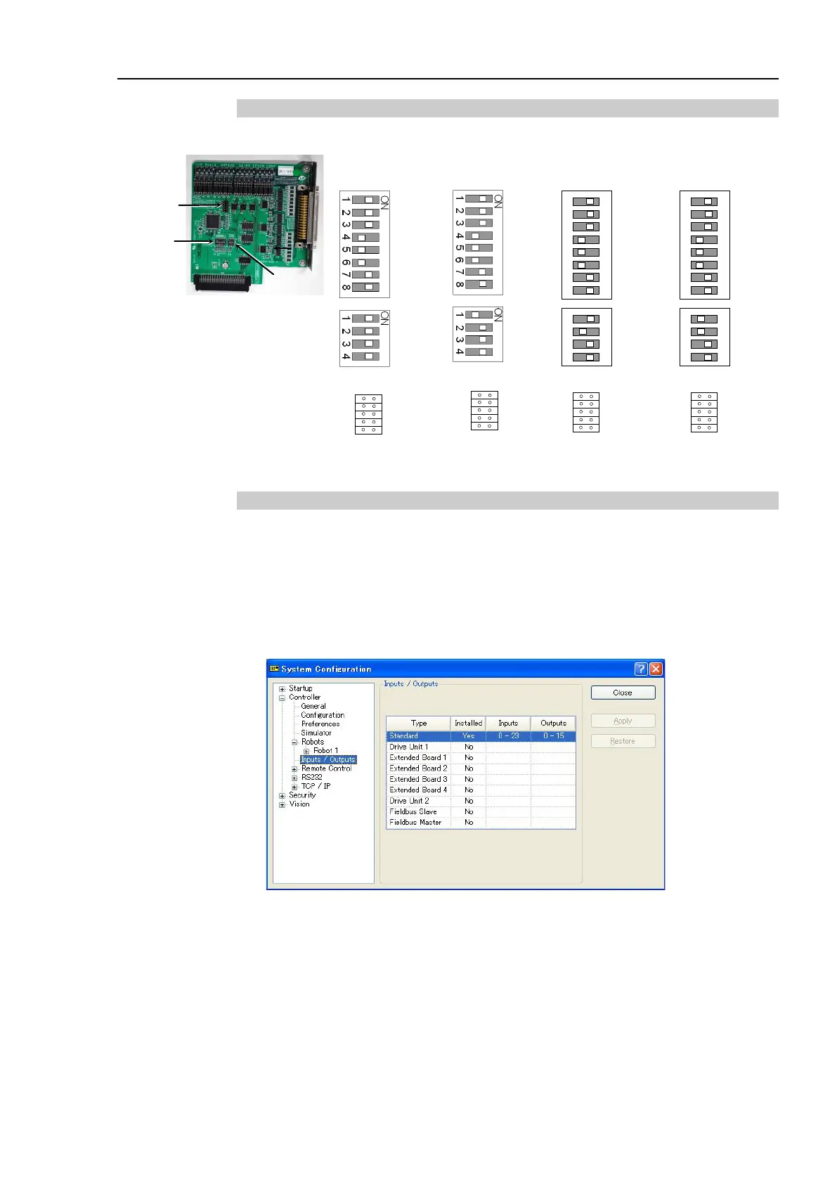
16.2.2 Board Configuration (Expansion I/O Board)
Board Appearance Switch and Jumper Configuration
Setup the DSW1 and DSW2. CN3 is all open.
st
nd
rd
th
SW1
SW2
SW3
SW4
SW5
SW6
SW7
SW8
SW1
SW2
SW3
SW4
SW5
SW6
SW7
SW8
SW8
SW7
SW6
SW5
SW4
SW3
SW2
SW1
SW8
SW7
SW6
SW5
SW4
SW3
SW2
SW1
16.2.3 Confirmation with EPSON RC+ 7.0 (Expansion I/O Board)
When an expansion I/O board is mounted to the option unit, the Controller software
automatically identifies the expansion I/O board. Therefore, no software configuration is
needed.
Correct identification can be confirmed from EPSON RC+ 7.0.
(1) Select the EPSON RC+ 7.0 menu-[Setup]-[System Configuration] to display the
[System Configuration] dialog.
(2) Select [Controller]-[Inputs / Outputs].
(3) Make sure that “Yes” is displayed in the Installed column.
The expansion I/O board is identified by the Controller software. Corresponding Input
and Output is available.
 Loading...


