Installation 2. Installation
28 RC700 Series Rev.3
2.5.2 Installation
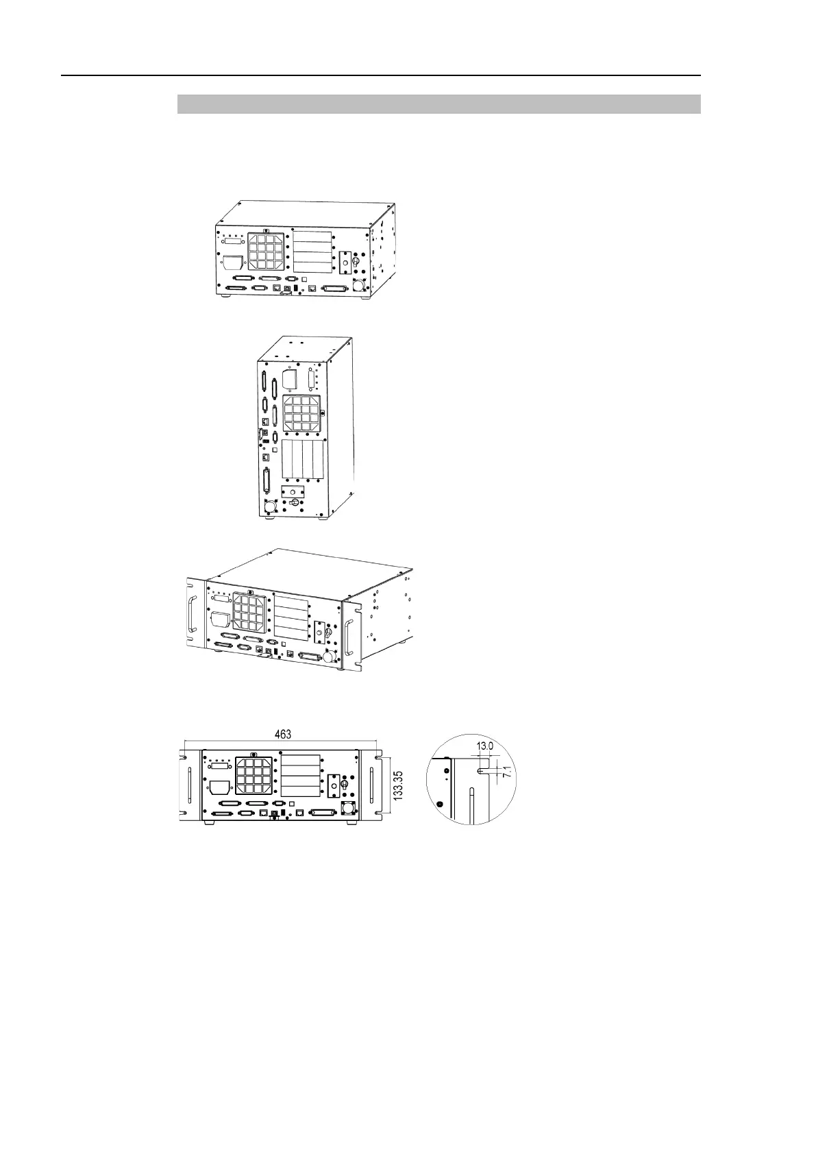
Install the Control unit and Drive unit on a flat surface such as wall, floor, and Controller
box in the direction shown in (A) to (C).
(A) Flat mounting
(Figure: RC700)
(B) Upright mounting
*
The rubber foot needs to be
replaced.
Attach the
rubber foot with the flat
side facing the controller.
The size of the screw that secure the
rubber foot is M4×8.
When replacing the rubber foot, be
careful not to lose the screw. Also, do
not use a screw of size other than
M4×8.
(C) Rack mounting
* A plate for rack mounting is required.
For Control Unit and Drive Unit installation to the Controller box or the base table, process
screw hole drilling as follows.
 Loading...


