Functions 15. R-I/O Connector
RC700 Series Rev.3 165
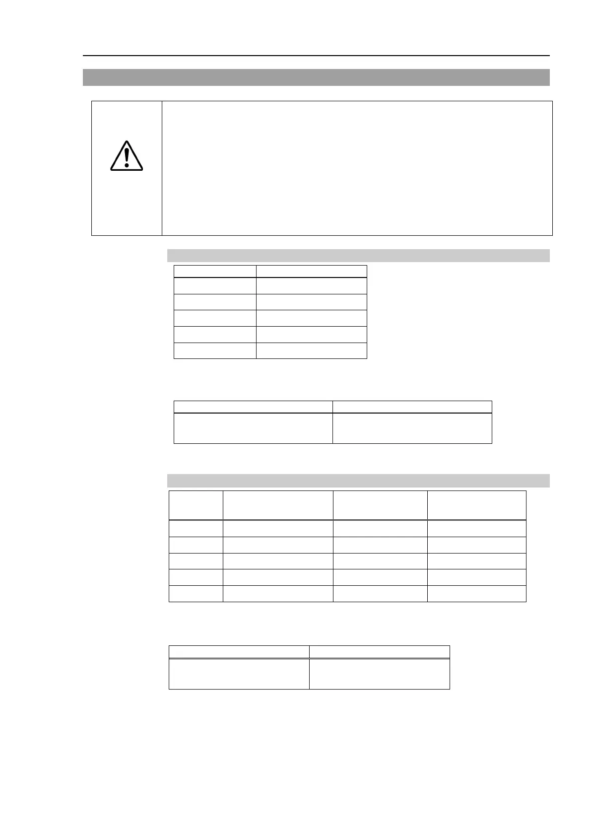
15.2 Pin Assignments
CAUTION
When using R-I/O
connector, be careful of the following points. If you use the
R-
I/O connector without meeting the necessary conditions, it may cause the
system failure and/or safety problems.
- Use a shielded cable and route the cables as far from the surrounding
noise sources as possible.
For details, refer to 3.5 Noise Countermeasures.
- Make sure to check the cable routing before turning ON the power
15.2.1 Pin Assignments for Control Unit
9 INPUT No24-1
10 INPUT No24-2
11 INPUT No25-1
12 INPUT No25-2
* For the pins 1 to 8 and 13 to 15, do not connect anything.
R-I/O Connector (Controller side)
D-sub 15 male pin
Screwlock #4 - 40
15.2.2 Pin Assignments for Drive Unit
Pin No.
Signal Name
(Drive Unit 1)
Signal Name
(Drive Unit 2)
Signal Name
(Drive Unit 3)
1 INPUT No.56-1 INPUT No.280-1 INPUT No.312-1
3 INPUT No.57-1 INPUT No.281-1 INPUT No.313-1
4 INPUT No.57-2 INPUT No.281-2 INPUT No.313-2
*
* For the pins 5 to 15 , do not connect anything.
R-I/O Connector
(Drive Unit side)
D-sub 15 male pin
 Loading...


