EPSON Stylus CX7300/CX7400/DX7400/NX200/TX200 series/SX200 series/Stylus CX8300/CX8400/DX8400/NX400/TX400 series/SX400 series Revision C
OPERATING PRINCIPLES Overview 46
Confidential
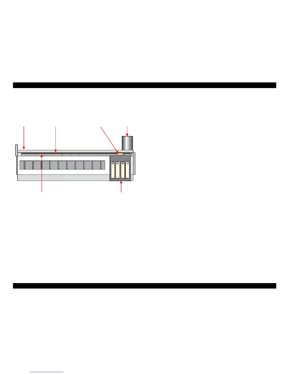
2.1.4 Carriage Mechanism
The carriage mechanism components include the carriage unit (including printhead,
CR encoder sensor), CR motor, timing belt, and CR scale.
The operating principles of the carriage mechanism are described below.
Figure 2-7. Carriage Mechanism
2.1.4.1 CR Motor Control
This printer employs closed-loop control, via the CR motor and an encoder, to control
the carriage speed and position. Since the CR motor is DC motor, the printer controls
the motor in the following methods in order to ensure stable print quality.
Heat control
The heat control over the CR motor is carried out based on the electrical
characteristic of the motor such as torque constants, coil resistance and power
supply voltages.
CR motor drive dispersion measurement sequence
Variations in torque constant, coil resistance and power supply voltage of the
motor are measured in a CR motor drive dispersion measurement sequence when
the CR mechanical load is in the initial state and saved into the EEPROM.
According to the variations measured in the sequence, the voltage is corrected to
make the drive current value constant reducing an individual difference.
CR measurement sequence
To set the appropriate drive voltage for the CR motor in accordance with variation
of the CR motor mechanical load, the printer runs a CR measurement sequence
and stores the measured data into the EEPROM at power-on or in an ink cartridge
replacement sequence. A fatal error occurs if the printer detects that too much load
is applied to the CR motor.
The above control and sequences enable to correct the drive voltage for the CR motor
based on the mechanical load and the electrical characteristic of the motor. According
to the corrected drive voltage, heating value of the motor is calculated. The printer
automatically provides wait time per CR path during printing when the predetermined
heating value is reached.
2.1.4.2 Carriage Home Position Detection
Like the previous model, the carriage home position is detected by the CR motor drive
electric current and carriage speed/position signals sent from the CR encoder. The
detection sequence performed at power-on is described below.
1. Drives the CR motor to move the carriage until it contacts with the right
frame, and then stops the CR motor. The carriage position is set as a position
specified number of counts rightward from the home position.
2. Moves the carriage again to the carriage lock position to check the lock for
proper operation.
3. The printer starts to monitor the carriage position through the CR encoder.
The printer causes a fatal error if too much load on the CR motor is detected due to
obstruction on the carriage path or if no carriage position information is obtained due to
CR encoder or CR scale failure.

 Loading...


