EPSON Stylus CX7300/CX7400/DX7400/NX200/TX200 series/SX200 series/Stylus CX8300/CX8400/DX8400/NX400/TX400 series/SX400 series Revision C
DISASSEMBLY/ASSEMBLY Disassembling the Printer Mechanism 120
Confidential
4.5.12 CR Motor
Parts/Components need to be removed in advance
Document Cover/ASF Cover/Scanner Unit/Panel Unit/Upper Housing/Card Slot
Cover/Lower Housing/Main Board Unit/Left Frame/Front Frame/Right Frame
Removal procedure
1. Turn the Spur Gear 51.5 to release the Carriage Lock, and move the CR Unit
to the center.
(Refer to 4.5.1 Printhead Step1 (p107))
2. Release the CR Motor cable from the notches (x3) of the Base Frame and the
hooks (x3) of the Main Frame, and then pull out the cable through the hole of
the Base Frame.
Figure 4-66. Removing the CR Motor (1)
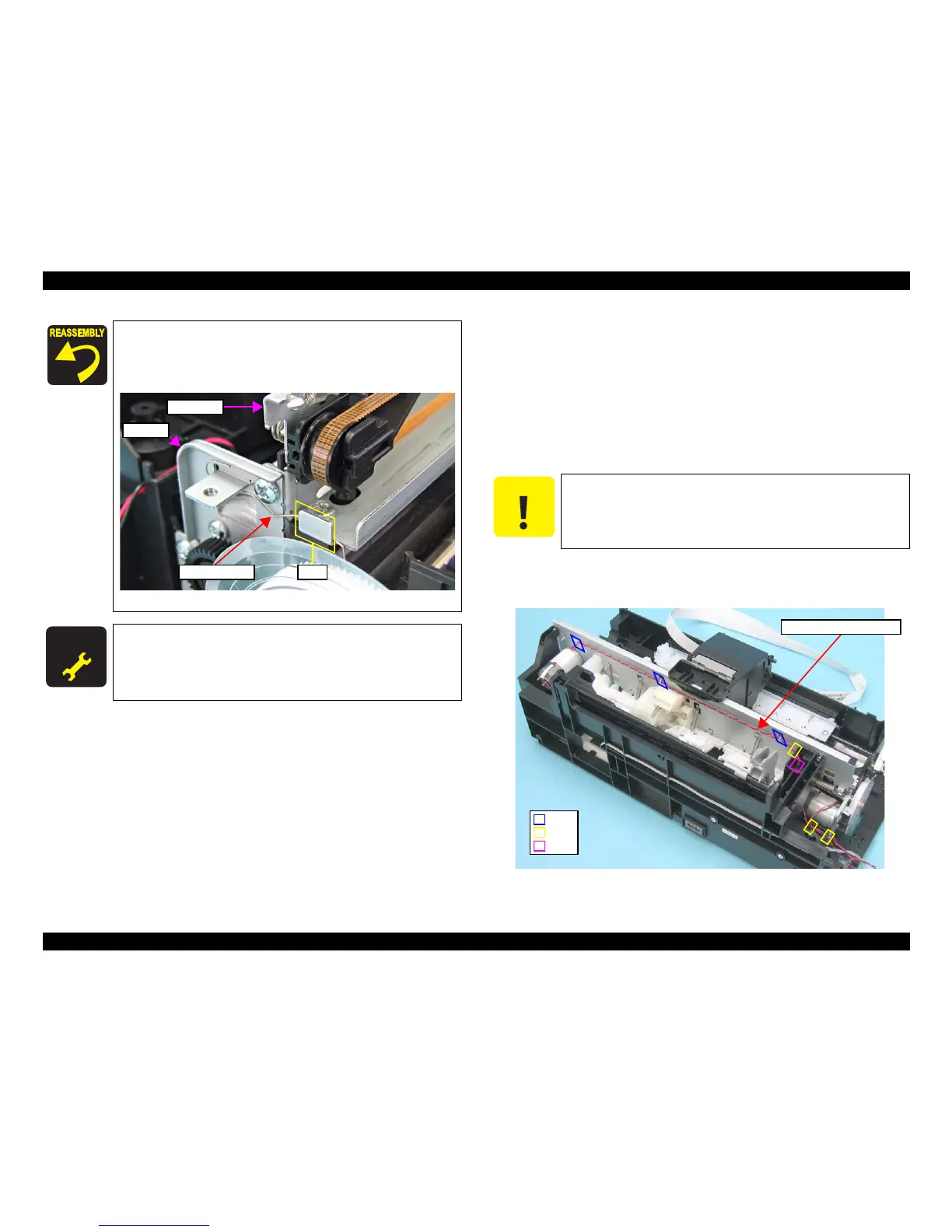
2. Pass the Grounding Spring along the inner side of the
hook of the Main Frame.
3. Ground the smaller U-shaped end of the Grounding
Spring with the undersurface of the frame for PF Motor.
Figure 4-65. Installing the Grounding Spring (2)
Whenever the PF Motor is removed/replaced, the required
adjustments must be carried out.
• Chapter 5 “ ADJUSTMENT” (p.141)
Be careful not to damage the CR Motor cable when releasing the
cable from the hooks of the Main Frame.

 Loading...


