EPSON Stylus CX7300/CX7400/DX7400/NX200/TX200 series/SX200 series/Stylus CX8300/CX8400/DX8400/NX400/TX400 series/SX400 series Revision C
DISASSEMBLY/ASSEMBLY Disassembling the Printer Mechanism 124
Confidential
4.5.14 CR Unit
Parts/Components need to be removed in advance
Document Cover/ASF Cover/Scanner Unit/Panel Unit/Upper Housing/Card Slot
Cover/Lower Housing/Main Board Unit/Left Frame/Front Frame/Right Frame/CR
Motor/CR Scale/Hopper/Main Frame Assy/Printhead
Removal procedure
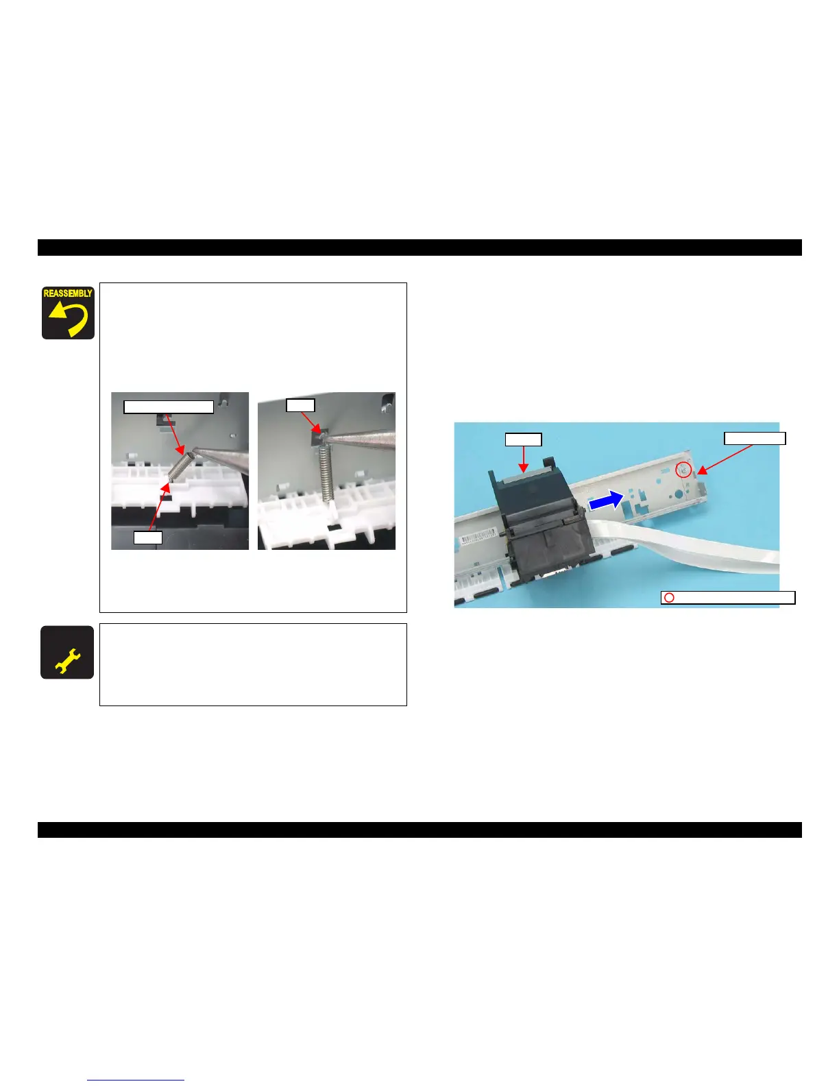
1. Remove the screw (x1) that secures the CR Scale Holder, and remove the CR
Scale Holder.
2. Move the CR Unit in the direction of the arrow to remove the CR Unit.
Figure 4-76. Removing the CR Unit (1)
3. Release the Timing Belt from the groove of the CR Unit.
Tighten the screws in the order given in Figure 4-73.
Follow the steps below to install the Extension Spring 10.99 to
the Upper Paper Guide.
1. Attach the one end of the Extension Spring 10.99 to the
hook of the Upper Paper Guide.
2. Attach the other end of the Extension Spring 10.99 to the
hook of the Main Frame with longnose pliers.
Figure 4-75. Installing the Extension Spring 10.99
Be sure to install the Grounding Spring referring to Figure
4-64 and Figure 4-65.
Whenever the Main Frame is removed/replaced, the required
adjustments must be carried out.
• Chapter 5 “ ADJUSTMENT” (p.141)
After replacing the Main Frame, be sure to perform the
specified lubrication.
• Chapter 6 “ MAINTENANCE” (p.151)

 Loading...


