EPSON Stylus CX7300/CX7400/DX7400/NX200/TX200 series/SX200 series/Stylus CX8300/CX8400/DX8400/NX400/TX400 series/SX400 series Revision C
OPERATING PRINCIPLES Scanner Mechanism 56
Confidential
2.2 Scanner Mechanism
The major components of the scanner mechanism of EPSON Stylus CX7300/CX7400/
DX7400/NX200/TX200/TX203/TX209/SX200/SX205 and Stylus CX8300/CX8400/
DX8400/NX400/TX400/TX405/TX409/SX400/SX405 are the scanner carriage unit
and the scanner motor.
2.2.1 Scanner Carriage Mechanism
2.2.1.1 Scanner Carriage Unit Overview
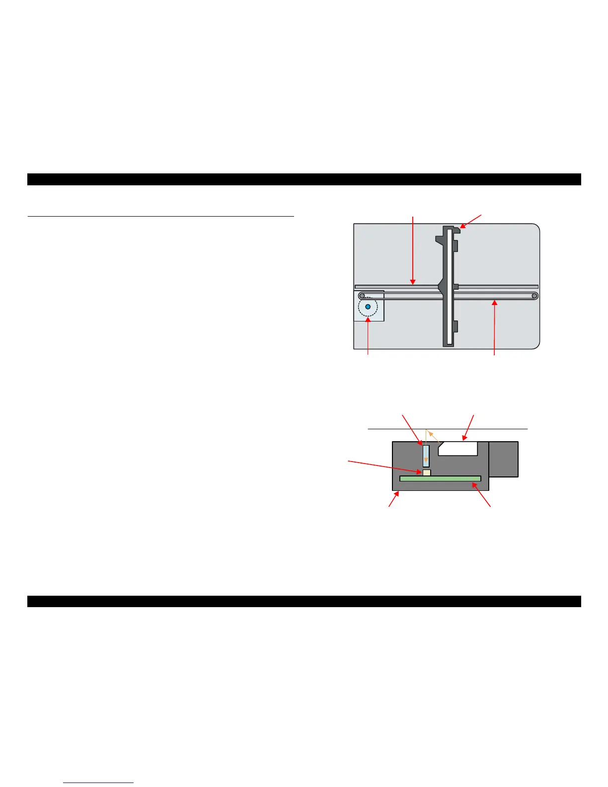
The Scanner Carriage Unit is constructed of a CIS Board (including linear CCD), Rod
Lens Array, LED (light source), etc.
CIS Board
CIS Board contains the sensing elements that are placed across the entire width of
an original. The sensing elements, which does not install a color filter, read an
original through the Rod Lens Array by turning on red, green, and blue light-
emitting diodes (LEDs) alternately. It is not the CIS Board but the Main Board that
converts the analog light signal read by the Rod Lens Array into digital signal.
Rod Lens Array
A number of rod-shaped lenses, which are arranged on the sensing elements, are
also placed across the entire width of an original. These lenses read the light
reflected from the original that is produced by the light source (LEDs) and pass the
information to the sensing elements. Compared to conventional CCD method, this
optical system allows the focal length (distance between sensor and image
scanned) to be shallow. Therefore, an original to be scanned should be brought
close to the document glass. The optical system, in addition, is 1:1, (there is no
optical reduction or enlargement) and this results in a scanner offering the solid
performance in terms of accuracy.
LED
Three color LEDs (the three colors being red, green, and blue) illuminate the line
to be scanned in the document. Unlike cold cathode fluorescent lamp used in CCD
method, using LEDs requires no warm-up time and allows the CIS to be highly
power efficient.
Figure 2-20. Scanner Mechanism
Figure 2-21. Scanning image

 Loading...


