EPSON Stylus CX7300/CX7400/DX7400/NX200/TX200 series/SX200 series/Stylus CX8300/CX8400/DX8400/NX400/TX400 series/SX400 series Revision C
DISASSEMBLY/ASSEMBLY Disassembling the Printer Mechanism 126
Confidential
4.5.15 Upper Paper Guide
Parts/Components need to be removed in advance
Document Cover/ASF Cover/Scanner Unit/Panel Unit/Upper Housing/Card Slot
Cover/Lower Housing/Main Board Unit/Left Frame/Front Frame/Right Frame/CR
Motor/CR Scale/Hopper/Main Frame Assy
Removal procedure
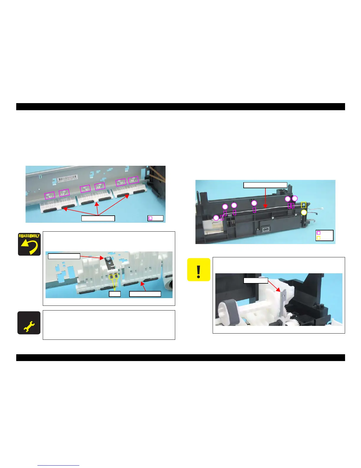
1. Release the hooks (x6), and remove the Upper Paper Guide.
Figure 4-80. Removing the Upper Paper Guide (1)
4.5.16 ASF Unit
Parts/Components need to be removed in advance
Document Cover/ASF Cover/Scanner Unit/Panel Unit/Upper Housing/Card Slot
Cover/Lower Housing/Main Board Unit/Left Frame/Front Frame/Right Frame/CR
Motor/CR Scale/Hopper/Main Frame Assy
Removal procedure
1. Release the PE Sensor cable from the notches (x6) of the Base Frame and pull
out the cable from the hole (x1).
Figure 4-82. Releasing the PE Sensor Connector Cable
When installing the Upper Paper Guide, attach the legs (x2) of the
antistatic cloth into the holes (x2) of Upper Paper Guide as shown
in the figure below.
Figure 4-81. Installing the Upper Paper Guide
Whenever the Upper Paper Guide is removed/replaced, the
required adjustments must be carried out.
• Chapter 5 “ ADJUSTMENT” (p.141)
When performing the following steps, be cautious not to get
injured with the sharp edges of the Frame Support.
Figure 4-83. Sharp Edges of the Frame Support

 Loading...


