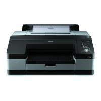
Epson Stylus Pro 4900/Epson Stylus Pro 4910 Revision A
DISASSEMBLY & ASSEMBLY Parts Diagram 106
Confidential
Figure 3-4. Electric Circuit Components
LED Board
(p166)
Control Panel Board
(p167)
Main Board
(p152)
Communicates with the computer.
Processes received data.
Controls the printer mechanism.
Stores the correction values and various counters.
Network Board
(p155)
Communicates across a network
Power Supply Board
(p159)
Generates the DC voltage for this
printer from the AC power
supply.
SUB Board
(p161)
Relays the connection between the Main Board
Assy and electric parts/components. See “
Connection Diagram” (p434) for specific
connections to the concerning parts/components.
SUB-C Board
(p163)
Relays the connection between the Main Board
Assy and electric parts/components. See “
Connection Diagram” (p434) for specific
connections to the concerning parts/components.
SUB-B Board
(p162)
Relays the connection between the Main Board
Assy and electric parts/components. See “
Connection Diagram” (p434) for specific
connections to the concerning parts/components.
SUB-D Board
(p164)
Relays the connection between the
Main Board Assy and electric parts/
components on the Roll Unit. See “
Connection Diagram” (p434) for
specific connections to the concerning
parts/components.
AID Board
(p165)
The board to perform the AID
function which detects dot
missing automatically.
 Loading...
