5-8 Adjustment and Setting Rev. B
Confidential
Note:
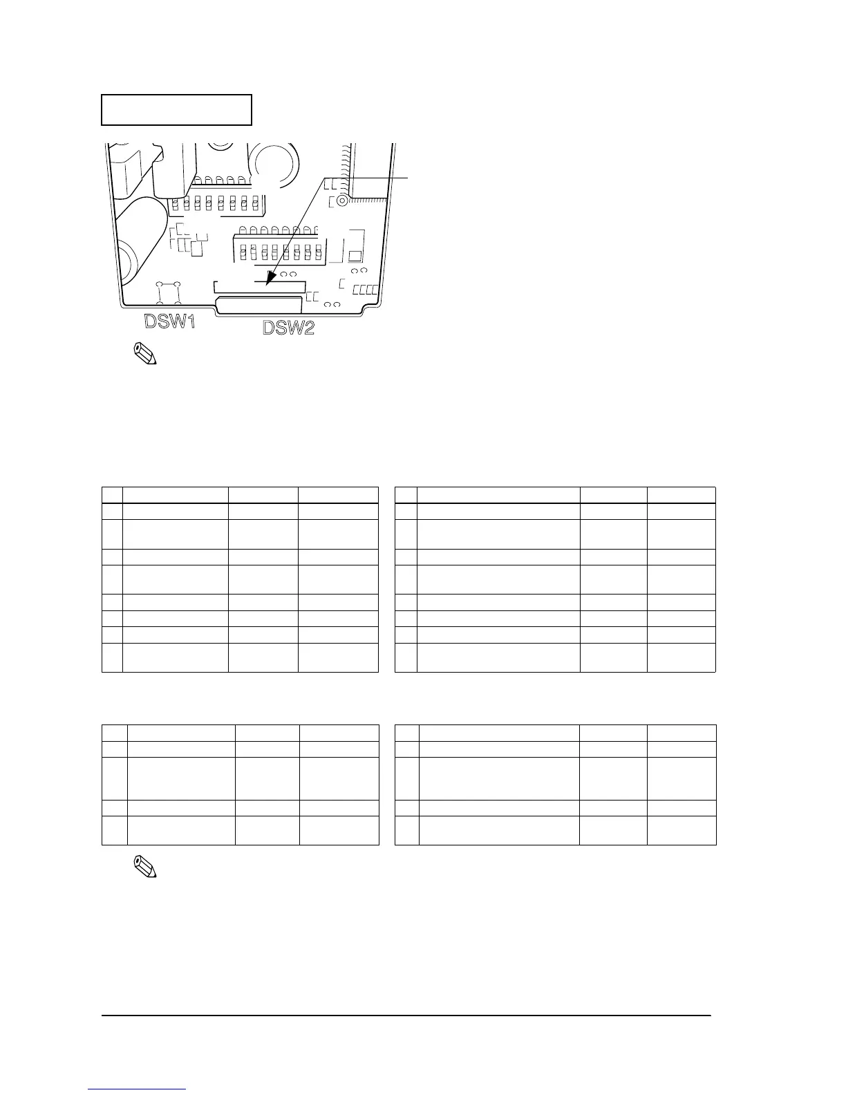
The switch functions are shown in the following sections.
US DIP switch functions are slightly different from the STD functions.
STD Tables
Note:
See the tables on the next page when the letters in the illustration above are “US.”
See “Notes for DIP Switch 2-1” on page 5-9 for further information on the settings for DIP SW 2-1.
When you use a serial interface model with 1200 bps, 2400 bps, or 19200 bps, adjust the “serial interface
selection“ DIP switch function and the “serial communication condition“ memory switch.
Serial Model
(DIP Switch 1) (DIP Switch 2)
SW Function On Off SW Function On Off
1 Data receive error Ignored Prints “?” 1 Print column selection 42/35 40/33
2 Receive buffer
capacity
40 bytes 4KB 2 Reserved
(autocutter enabled/ disabled)
Fixed to On —
3 Handshaking XON/XOFF DTR/DSR 3 Reserved — Fixed to Off
4 Word length 7 bits 8 bits 4 Serial interface selection Memory
switch
DIP switch
5 Parity check Yes No 5 Reserved — Fixed to Off
6 Parity selection Even Odd 6 Reserved — Fixed to Off
7 Transmission speed 4800 bps 9600 bps 7 Pin 6 reset signal Used Not used
8 Busy condition Receive
buffer full
Receive buffer
full or offline
8 Pin 25 reset signal Used Not used
Parallel / USB / Ethernet Model (Not for Serial Models)
(DIP Switch 1) (DIP Switch 2)
SW Function On Off SW Function On Off
1 Auto line feed Enabled Disabled 1 Print column selection 42/35 40/33
2 Receive buffer
capacity
40 bytes 4KB 2 Reserved
(Autocutter enabled/
disabled)
Fixed to On —
3~7 Reserved — Fixed to Off 3~7 Reserved — Fixed to Off
8 BUSY condition Receive
buffer full
Receive buffer
full or offline
8 Pin 31 reset signal Used Not used
Look at the numbers and letters in the area indicated in
the illustration. If the last letters are “US,” use the “US” tables
on the next page. If the last letters are “STD,” use the “STD”
tables below.
ON
OFF
ON
OFF
 Loading...


