ESAB FABRICATOR 141i
INSTALLATION, OPERATION AND SETUP 3-12 Manual 0-5420
WARNING
Before connecting the work clamp to the work piece, make sure you have ceased feeding wire so prema-
ture arcing will not occur.
The electrode wire will be at welding voltage potential while it is being fed through the system.
Keep MIG Gun away from eyes and face.
Art #
A-10359_AB
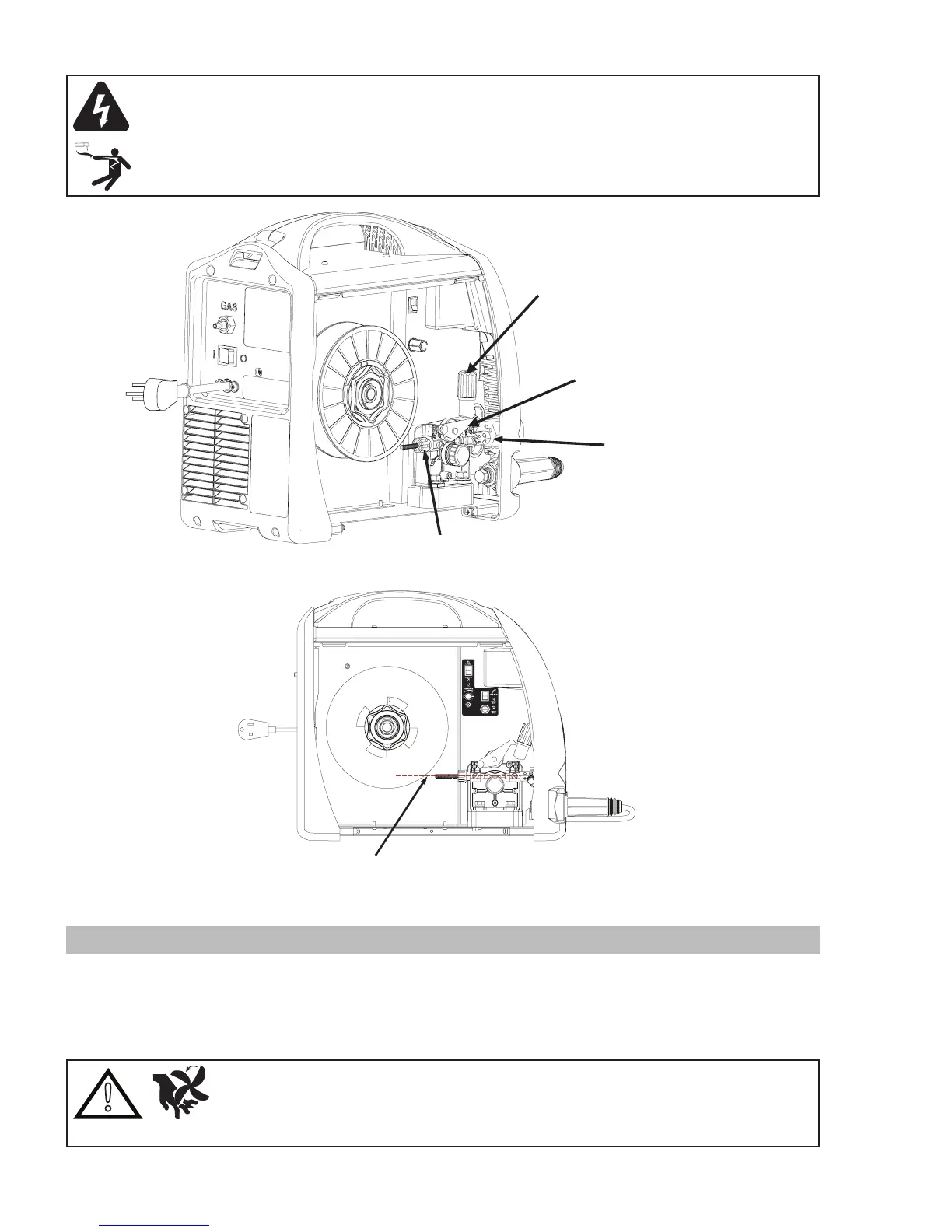
Outlet Guide
Inlet Guide
Wire Drive Tension Screw
Pressure Roller Arm
Figure 3-9: Wire Drive Assembly Components
MIG Welding Wire
Art #
A-10360
Figure 3-10: MIG Welding Wire - Installation
3.13 Installing 4" (100mm) Diameter Spool
As delivered from the factory, the Power Source is fitted with a Wire Spool Hub which accepts a 8" (200mm) diameter spools. In
order to fit a 4" (100mm) diameter spool assemble parts in the sequence shown below in Figure 3-11.
Adjustment of the nut with nylon insert will control the MIG Wire Spool Brake. Clockwise rotation of this nut with nylon insert
tightens the brake. The brake is correctly adjusted when the spool stops within 4" (100mm) to 8" (200mm) (measured at the outer
edge of the spool) after MIG Gun trigger is released. Wire should be slack without becoming dislodged from the spool.
!
CAUTION
Overtension of brake will cause rapid wear of mechanical WIRE FEED parts, overheating of
electrical components and possibly an increased incidence of electrode wire Burnback into
contact tip.
 Loading...