ESAB FABRICATOR 141i
INSTALLATION, OPERATION AND SETUP 3-14 Manual 0-5420
3.15 Feed Roller Pressure Adjustment
The pressure (top) roller applies pressure to the grooved
feed roller via an adjustable pressure screw. These devices
should be adjusted to a minimum pressure that will provide
satisfactory wire feed without slippage. If slipping occurs, and
inspection of the wire contact tip reveals no wear, distortion or
burn back jam, the conduit liner should be checked for kinks
and clogging by metal flakes and debris. If it is not the cause of
slipping, the feed roll pressure can be increased by rotating the
pressure screw clockwise.
WARNING
Before changing the feed roller ensure
that the Electricity Supply to the Power
Source is switched off.
!
CAUTION
The use of excessive pressure may cause
rapid wear of the feed rollers, shafts and
bearing.
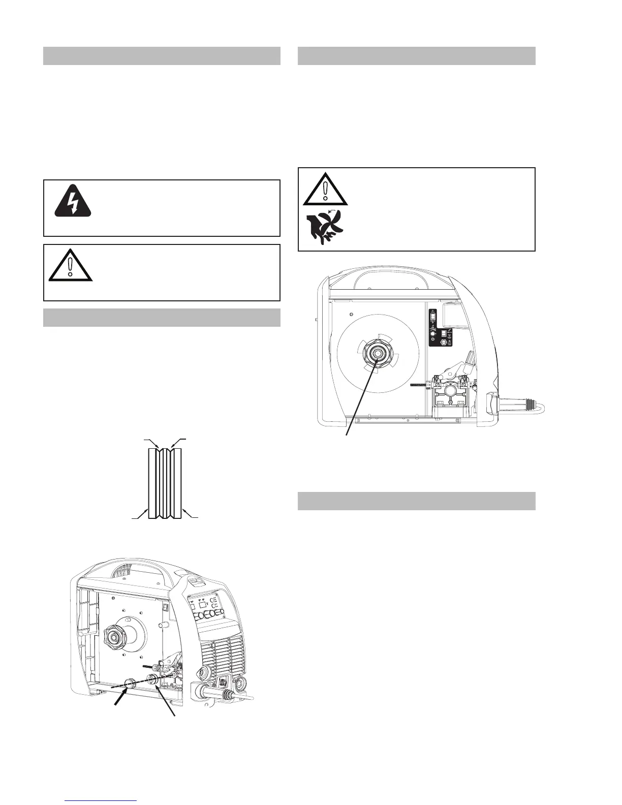
3.16 Changing the Feed Roll
To change feed roll remove the feed roll retaining screw by
turning in an counterclockwise direction. Once the feed roll is
removed then to replace feed roll simply reverse these direc-
tions.
A dual groove feed roller is supplied as standard. It can accom-
modate 023"(0.6mm) -.030" (0.8mm) diameter hard wires.
Select the roller required with the chosen wire size marking
facing outward.
GROOVE “B”GROOVE “A”
GROOVE “A” SIZE
GROOVE “B” SIZE
A-09583
Figure 3-13: Dual Groove Feed Roller
Feed Roll
Retaining Screw
Feed Roll
Art #
A-09584_AC
Figure 3-14: Changing the Feed Roll
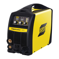
3.17 Wire Reel Brake
The wire reel hub incorporates a friction brake which is
adjusted during manufacture for optimum breaking. If it is
considered necessary, adjustment can be made by turning the
large nut inside the open end of the hub clockwise to tighten
the brake. Correct adjustment will result in the wire reel
circumference continuing no further than 3/8" (10mm) - 3/4"
(20mm) after release of the trigger. The electrode wire should
be slack without becoming dislodged from wire spool.
!
CAUTION
Overtension of brake will cause rapid
wear of mechanical WIREFEED parts,
overheating of electrical components
and possibly an increased incidence of
electrode wire Burnback into contact tip..
Wire Reel Brake Adjustment Nut
Art #
A-10361
Figure 3-15: Wire Reel Brake
3.18 Flowmeter/ Regulator Operation
With the flowmeter/ regulator connected to cylinder or pipeline,
and the adjustment screw/knob fully disengaged, pressurize as
follows:
1. Stand to one side of flowmeter/ regulator and slowly
open the cylinder valve. If opened quickly, a sudden
pressure surge may damage internal parts.
2. With valves on downstream equipment closed, adjust
flowmeter/ regulator to approximate working pres-
sure. It is recommended that testing for leaks at the
flowmeter/ regulator connection points be carried
out using a suitable leak detection solution or soapy
water.
3. Purge air or other unwanted welding grade shield-
ing gas from equipment connected to the flowmeter/
regulator by individually opening then closing the
equipment control valves. Complete purging may take
up to ten seconds or more, depending upon the length
and size of the hose being purged.
 Loading...