ESAB FABRICATOR 141i
BASIC WELDING GUIDE 4-14 Manual 0-5420
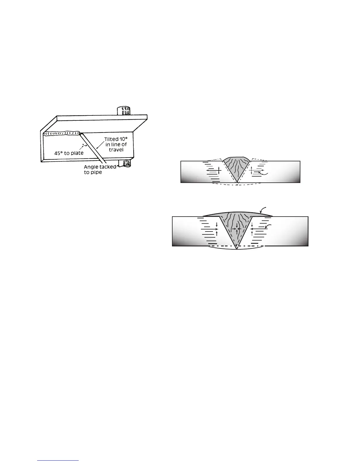
overhead position as shown in the sketch. The elec-
trode is held at 45º to the horizontal and tilted 10º in
the line of travel (Figure 4-28). The tip of the electrode
may be touched lightly on the metal, which helps to
give a steady run. A weave technique is not advisable
for overhead fillet welds. Use a 1/8"(3.2mm) E6013
Stick electrode at 100 amps, and deposit the first run
by simply drawing the electrode along at a steady
rate. You will notice that the weld deposit is rather
convex, due to the effect of gravity before the metal
freezes.
Art # A-07704
Figure 4-28: Overhead Fillet Weld
Distortion
Distortion in some degree is present in all forms of weld-
ing. In many cases it is so small that it is barely perceptible,
but in other cases allowance has to be made before welding
commences for the distortion that will subsequently occur. The
study of distortion is so complex that only a brief outline can
be attempted hear.
The Cause of Distortion
Distortion is caused by:
A. Contraction of Weld Metal:
Molten steel shrinks approximately 11 per cent in volume on
cooling to room temperature. This means that a cube of mol-
ten metal would contract approximately 2.2 per cent in each
of its three dimensions. In a welded joint, the metal becomes
attached to the side of the joint and cannot contract freely.
Therefore, cooling causes the weld metal to flow plastically,
that is, the weld itself has to stretch if it is to overcome the
effect of shrinking volume and still be attached to the edge
of the joint. If the restraint is very great, as, for example, in
a heavy section of plate, the weld metal may crack. Even in
cases where the weld metal does not crack, there will still
remain stresses "Locked-up" in the structure. If the joint
material is relatively weak, for example, a butt joint in 5/64"
(2.0mm) sheet, the contracting weld metal may cause the
sheet to become distorted.
B. Expansion and Contraction of Parent Metal in the
Fusion Zone:
While welding is proceeding, a relatively small volume of the
adjacent plate material is heated to a very high temperature
and attempts to expand in all directions. It is able to do this
freely at right angles to the surface of the plate (i.e., "through
the weld", but when it attempts to expand "across the weld"
or "along the weld", it meets considerable resistance, and
to fulfill the desire for continued expansion, it has to deform
plastically, that is, the metal adjacent to the weld is at a
high temperature and hence rather soft, and, by expanding,
pushes against the cooler, harder metal further away, and
tends to bulge (or is "upset". When the weld area begins
to cool, the "upset" metal attempts to contract as much as
it expanded, but, because it has been "upset" it does not
resume its former shape, and the contraction of the new
shape exerts a strong pull on adjacent metal. Several things
can then happen.
The metal in the weld area is stretched (plastic deforma-
tion), the job may be pulled out of shape by the powerful
contraction stresses (distortion), or the weld may crack, in
any case, there will remain "locked-up" stresses in the job.
Figures 4-29 and 4- 30 illustrate how distortion is created.
Art # A-07705_AB
Hot
Hot
Weld
Expansion with
compression
Cool
Figure 4-29: Parent Metal Expansion
Art # A-07706_AC
Weld
Permanent Upset
Contraction
with tension
Figure 4-30: Parent Metal Contraction
Overcoming Distortion Effects
There are several methods of minimizing distortion effects.
A. Peening
This is done by hammering the weld while it is still hot.
The weld metal is flattened slightly and because of this the
tensile stresses are reduced a little. The effect of peening
is relatively shallow, and is not advisable on the last layer.
B. Distribution of Stresses
Distortion may be reduced by selecting a welding sequence
which will distribute the stresses suitably so that they tend
to cancel each other out. See Figures 4-31 through 4-33 for
various weld sequences. Choice of a suitable weld sequence
is probably the most effective method of overcoming distor-
tion, although an unsuitable sequence may exaggerate it.
Simultaneous welding of both sides of a joint by two welders
is often successful in eliminating distortion.
C. Restraint of Parts
Forcible restraint of the components being welded is often
used to prevent distortion. Jigs, positions, and tack welds
are methods employed with this in view.
 Loading...