147
4.1 Set Up
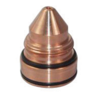
Select an appropriate condition from the process data (SDP File) and install recommended torch front-•
end parts (nozzle, electrode, etc.) See process data to identify parts and settings.
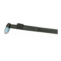
Position torch over material at desired start location. •
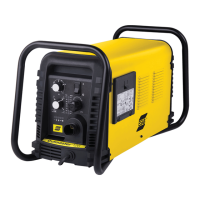
See Power Source Manual for proper settings. •
See Flow Control Manual for gas control procedures. •
See Control and Machine Manuals for startup procedures. •
4.1.1 Mirror Cutting
When mirror cutting, a reverse swirl gas bae and reverse diuser are required. These reverse parts will “spin”
the gas in the opposite direction, reversing the “good” side of the cut.
4.2 Cut Quality
A. Introduction
Causes aecting cut quality are interdependent. Changing one variable aects all others. Determining a solu-
tion may be dicult. The following guide oers possible solutions to dierent undesirable cutting results. To
begin select the most prominent condition:
4.2.2 Cut Angle, negative or positive
4.2.3 Cut Flatness
4.2.4 Surface nish
4.2.5 Dross
4.2.6 Dimensional Accuracy
Usually the recommended cutting parameters will give optimal cut quality, occasionally conditions may vary
enough that slight adjustments will be required. If so:
Make small incremental adjustments when making corrections.•
Adjust Arc Voltage in 5 volt increments, up or down as required.•
Adjust cutting speed 5% or less as required until conditions improve.•
SECTION 4 OPERATION
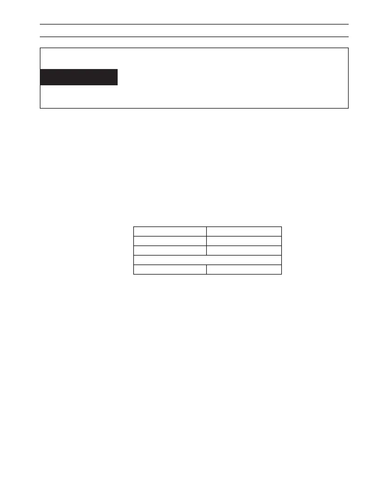
Oil And Grease Can Burn Violently!
on clean surface.
of oxygen under pressure.
WARNING
Reverse 4 Hole Bae P/N 0558002534
Reverse 8 x .047 Bae P/N 0558002530
Reverse 8 x .067 Bae P/N 20918
Reverse Diuser P/N 22496