MR & MRS OPERATION TABLES
Page 10 of 29 T-SM5f
Part 4
4.11 Before refitting ram cover, check that table
will raise and lower smoothly. If this is not the
case, the ram key is probably secured too tightly.
Release the key attachment bolts (4) slightly to
remove excessive friction, then retighten.
4.12 Check for signs of oil leaks. If table will
not pump to its full height, refill reservoir with
the Eschmann oil supplied with the table, in small
measures, lowering the table after each addition.
This will avoid the risk of introducing too much
oil into the hydraulic system.
4. MAINTENANCE
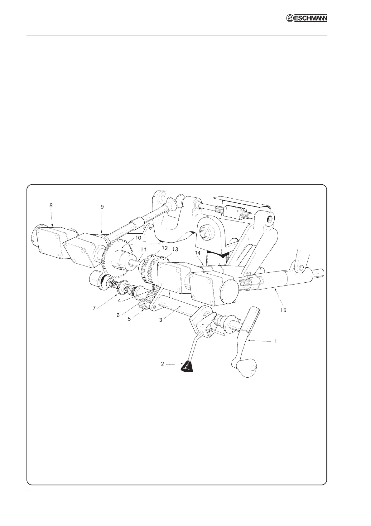
1. Main control handle 9. Pivot gear, lateral tilt
2. Gear selector lever 10. Drive gear, lateral tilt
3. Selector shaft 11. Gear shaft
4. Trendelenburg idler gear 12. Drive gear, break
5. Break idler gear 13. Drive gear, Trendelenburg
6. Gear selector unit 14. Trendelenburg screw and gearbox
7. Selector gear, lateral tilt 15. Break screw and gearbox (right hand)
8. Break screw and gearbox (left hand)
Fig. 6 Gearbox of MR operation table
Gears
4.13 Check function of gear selector lever in
conjunction with main control handle and ensure
that each table top movement is satisfactorily
achieved. Check to see if there is any excessive
play in table top in any particular direction (see
section 4.14 and 4.15). This applies particularly
to the two grub screws (4, Fig. 10) securing
screwed bush to screw housing on Trendelenburg
and Break screw assemblies. Check friction collar
adjustment on Trendelenburg and Break screw
gears (see sections 4.16-4.19); also check that