MR & MRS OPERATION TABLES
Page 16 of 29 T-SM5f
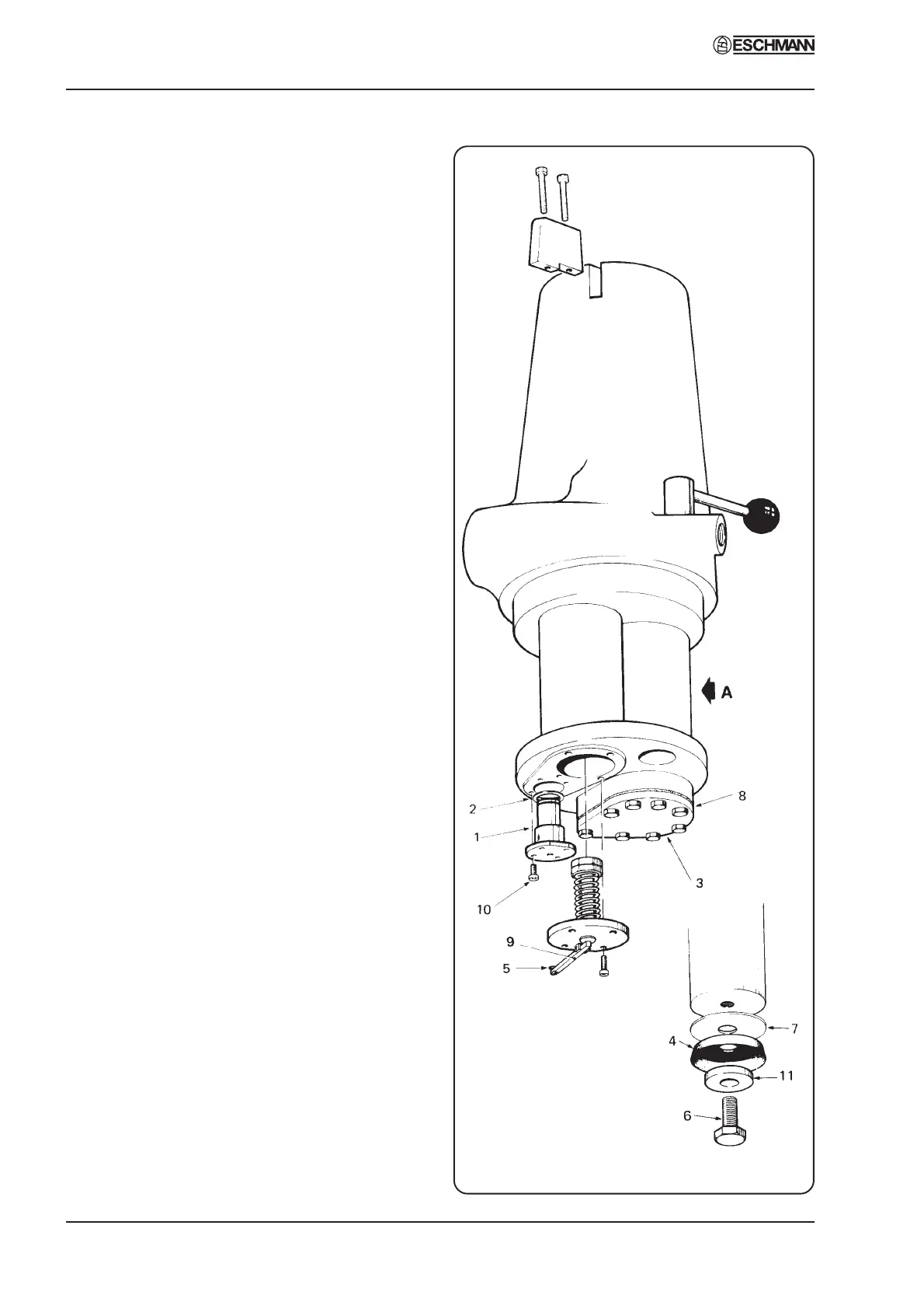
Fig. 13 Hydraulic cylinder assembly
Part 4
control handle in position with the three
screws when adjustment is correct.
ii Check the operation of the gas spring and
look for any signs of leakage. Replace the
gas spring (see section 4.59) if performance
is poor or there are signs of leakage. (Note
the Warnings and Cautions regarding gas
springs between sections 4.20 and 4.21).
iii Lubricate all moving parts using part number
670010.
iv On completion of routine checks on control
arm replace cover and check all functions.
Emergency operation - early MRS table only
4.22 This section only refers to tables with cable
operated control arms (i.e. pre Serial Number
1025). Refer to the latest version of the
Instructions for Use, Publication No. T-IM18 and
place the table in emergency operation. Check that,
with the emergency gear lever in the three
alternative positions, the table top will move in
the corresponding directions by use of the main
control handle.
Head/leg section and catches
4.23 Proceed as follows for old style sections
without gas spring supports, for sections with gas
springs refer to section 4.24.
Note: Gas spring supports were not fitted to head
sections of tables pre Serial Number 1026 for
MRS and pre Serial Number 676 for MR, or leg
sections of tables pre Serial Number 1017 for
MRS and pre Serial Number 315 for MR. Tables
with these Serial Numbers or later have gas spring
supports.
i Clean out any collected debris from the
recesses of the locking and guide pin push
button catches (4, Fig. 17) in the trunk
sections of the table. Refer to section 4.49 to
4.52 and dismantle each push button check
each component for damage or wear
replacing as necessary, Check spring-loaded
nylon plungers (2, Fig. 17) for smooth action.
Clean and lubricate the catch mechanism
then reassemble (again referring to section
4.49 to 4.52.) and test.
ii Lubricate rack and fine adjustment
movement of head/leg section.
4. MAINTENANCE