MR & MRS OPERATION TABLES
Page 14 of 29 T-SM5f
Part 4
hexagon (3) on the end of the leadscrew and
turning the torque screwdriver.
iv If the leadscrew rotates before the torque
screwdriver reaches 20-25 lbf.in. the friction
collar requires adjusting as (v) below. If the
leadscrew does not rotate the friction collar
setting is correct and requires no further
adjustment and the table can be reassembled.
v Adjust the friction collar by slackening the
single grub screw (4) that locks the torque
adjuster nut (5) and removing the three
screws (6) securing the cap ring (7) located
at the rear of the gearbox housing thus
exposing the torque adjusting nut (5). Locate
spanner (tool number T2097 Part No.
759652) onto the torque adjuster nut (5) and
tighten or slacken to gain the correct setting
(i.e. the torque setting is between that given
in (iii) above but operation of the
Trendelenburg handle is not too difficult).
vi Replace the cap ring (7) and secure using the
three screws (6), lock the torque adjuster nut
(5) by tightening the single grub screw (4)
and reassemble the table.
Chair and Break screw assembly friction
collars
4.19 Should the ‘Chair and Break’ screw friction
collars ever require adjustment, the procedure is
similar to that for the Trendelenburg screw
assembly (see 4.16 to 4.18), once the ‘Chair and
Break’ screw assembly has been released from
the gear shaft. (Note that MR tables with serial
number 2099 or below have the earlier design of
screw detailed in sections 4.16 to 4.18 and tables
above 2099 have the latest design screw. All MRS
tables have the early design ‘Chair and Break’
screw).
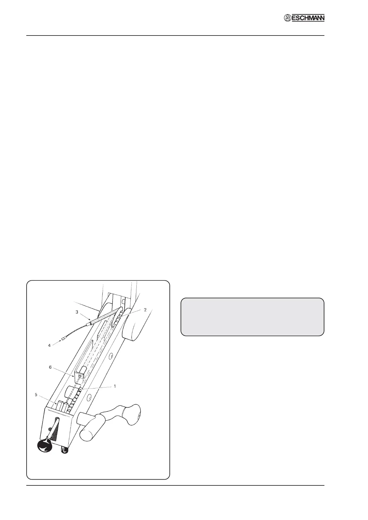
Control arm (cable type) - MRS only
4.20 The control arm of early tables were cable
operated and were fitted to tables with Serial
Number 1023 or earlier. Refer to Fig. 11 and
remove the control arm cover, then:
i Check chain links (1)
ii Check gears and keys (2)
iii Ensure lubrication of cable (3)
iv Check cable bends and cable nipples (4)
(also see Fig. 15).
Control arm (gas spring type) - MRS only
WARNING
Gas springs are filled with
high pressure gas.
DO NOT ATTEMPT TO OPEN THEM
CAUTION
Gas springs MUST NOT be
additionally lubricated.
4.21 Gas spring operated control arms have been
fitted to tables from Serial Number 1024 onwards.
Remove the extended head end control arm cover
(see Fig. 20) and carry out the following
procedures to ensure the correct function of the
control arm.
i Check gears and keys and that the chain
operates smoothly and is not loose. If the
chain is loose it can be adjusted by releasing
the three screws located around the main
control handle mounting plate. This plate is
eccentric and rotating it will alter the chain
tension and remove slack, lock the main
4. MAINTENANCE
Fig. 11 Control arm (early MRS table)