T-SM5f Page 19 of 29
MR & MRS OPERATION TABLES
Part 4
4. MAINTENANCE
completely loose then remove clamp and
ram release (see Fig. 12(d)).
iv Refer again to Fig. 14. Adjustment consists
of unscrewing, in a clockwise direction, the
two large lock nuts (4) on the end of the
release plunger (5) to allow more movement
of the ram release lever. This is in order to
cause the ball of the ball valve to be lifted
further and so release the table ram. (For a
more detailed explanation of the hydraulic
system, refer to section 4.60 and 4.61).
Note:This adjustment can only be made on a trial
and error basis. Each time an adjustment is
made the ram release must be refitted into
the cylinder and the pump lever tried and
held to ascertain whether the release screw
on the lever projects too far into the ball
valve, or still not enough. Care must be
taken to adjust this correctly as strain will
occur either side of the normal. As a guide,
the normal setting is 1/16in between release
screw and ball valve housing (approximately
the thickness of an engineer’s steel ruler).
v When the correct adjustment has been made,
lift the cylinder and table top bodily and
guide the cylinder back into the well of the
base. DO NOT ALLOW THE CYLINDER
TO DROP INTO THE BASE. When the
table is in an upright position and before
lowering it into the base, refit the locking
lever. This will prevent the escape of oil
from the cylinder. The table top should now
raise and lower normally.
Note:If it is found that the driving pin of the pump
pedal has been bent - too badly for any
adjustment - a new pump lever must be
fitted.
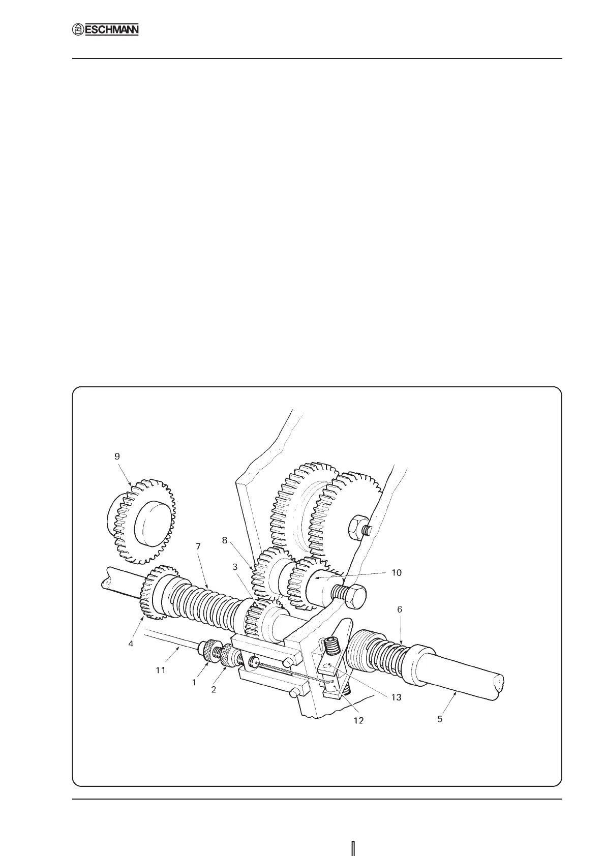
Fig. 15 Control arm cable adjustment/replacement - MRS table pre Serial No. 1024