MR & MRS OPERATION TABLES
Page 24 of 29 T-SM5f
vi Complete drilling through handle, using a
wooden block for the drill to break into -
hence protecting the plating on the handle.
vii Use a tapered reamer to shape out the holes
for the taper pin. Fit new taper pin (1)
ensuring that it is inserted through the aligned
holes the correct way round.
viii Remove the distance piece from the selector
shaft (see ‘ii’ above)
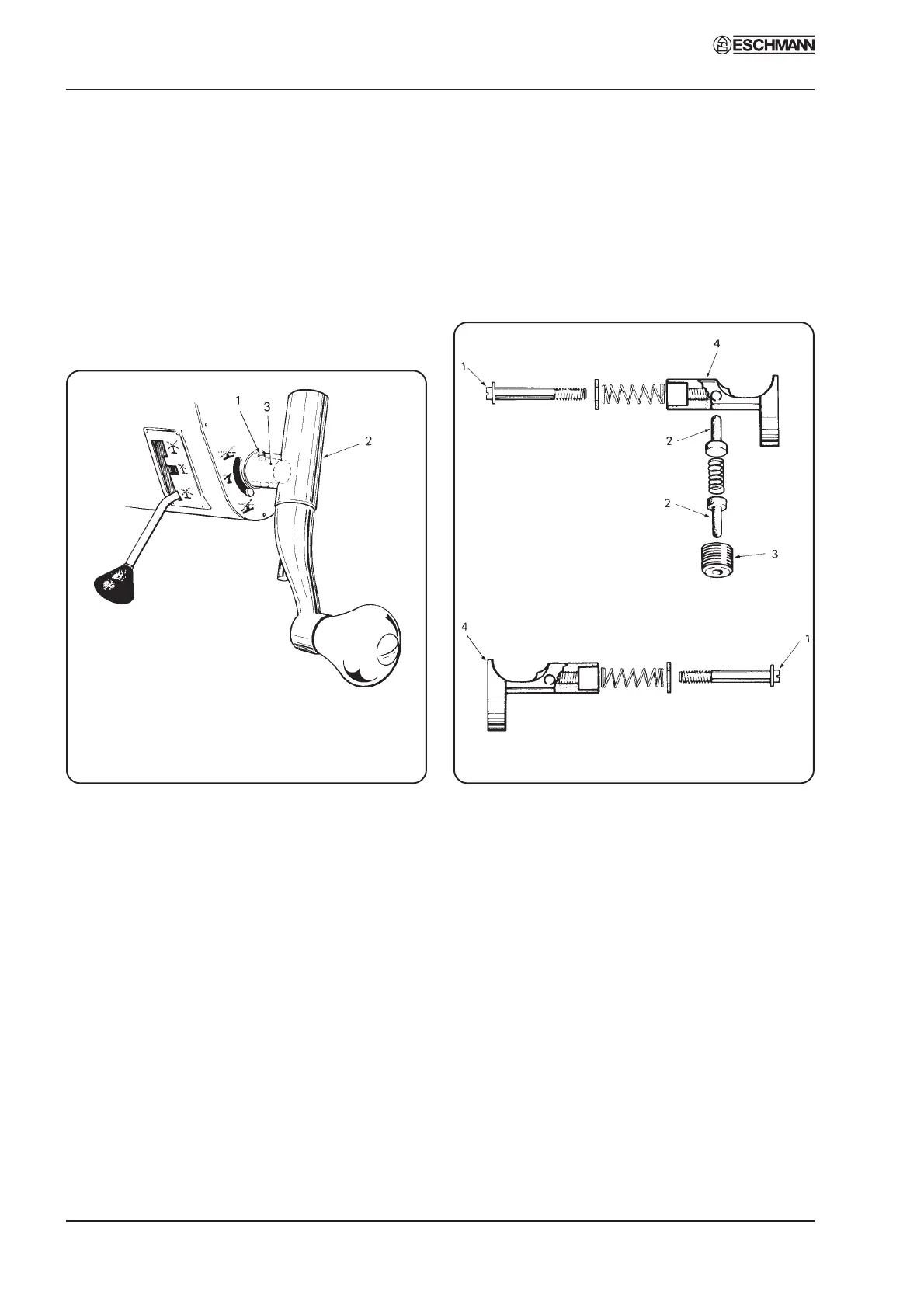
Fig. 16 Replacing a control handle
Replace push-button catches - head / leg section
4.48 Should it be necessary to gain access to the
push-button catches for cleaning, lubrication or
replacement, first remove the appropriate section
(head or leg section) and apply a screwdriver to
the slotted end of the threaded spindle of the catch
(1, Fig 17). The catch spindles at the lower trunk
end of the table are readily visible (at the end of
the section underneath the radiographic top) but
to gain access to those at the upper trunk end it is
necessary to detach the radiographic top of the
upper trunk section by removing the socket head
screws.
4.49 The right hand push-button ‘A’ catch
operates in conjunction with a spring loaded
plunger (2, Fig. 17) which, in turn, operates to
(A)
(B)
retain the push-button in the ‘release’ position if the
button is pressed with the head or leg section in
position.
4.50 The left hand push-button ‘B’ catch has no
retaining plunger and must be pressed in
continuously while the head/leg section (or table
accessory, where appropriate) is being withdrawn.
Fig. 17 Catch mechanism for leg section
4.51 Ensure that the spring loaded plunger
(2, Fig. 17) referred to in section 4.49 moves freely
in its socket. If the plunger has become damaged
or distorted such as to impair free movement, it
should be replaced. To remove plunger, unscrew
threaded bush (3, Fig. 17).
4.52 To remove a faulty latch, unscrew threaded
spindle (1, Fig.17) completely and lift away push
button/latch assembly (4, Fig.17). If the latch has
scored the attachment pins of head/leg section the
complete push-button/latch should be replaced.
Repair any scoring on attachment pins with a fine
file and/or crocus cloth before placing in service
again. It is advised that setting tool number T1612
Part No. 759579 is used when finally adjusting
push buttons as follows:
i Push setting tool T1612 into guide pin hole
up to the edge of the groove.