T-SM5f Page 7 of 29
MR & MRS OPERATION TABLES
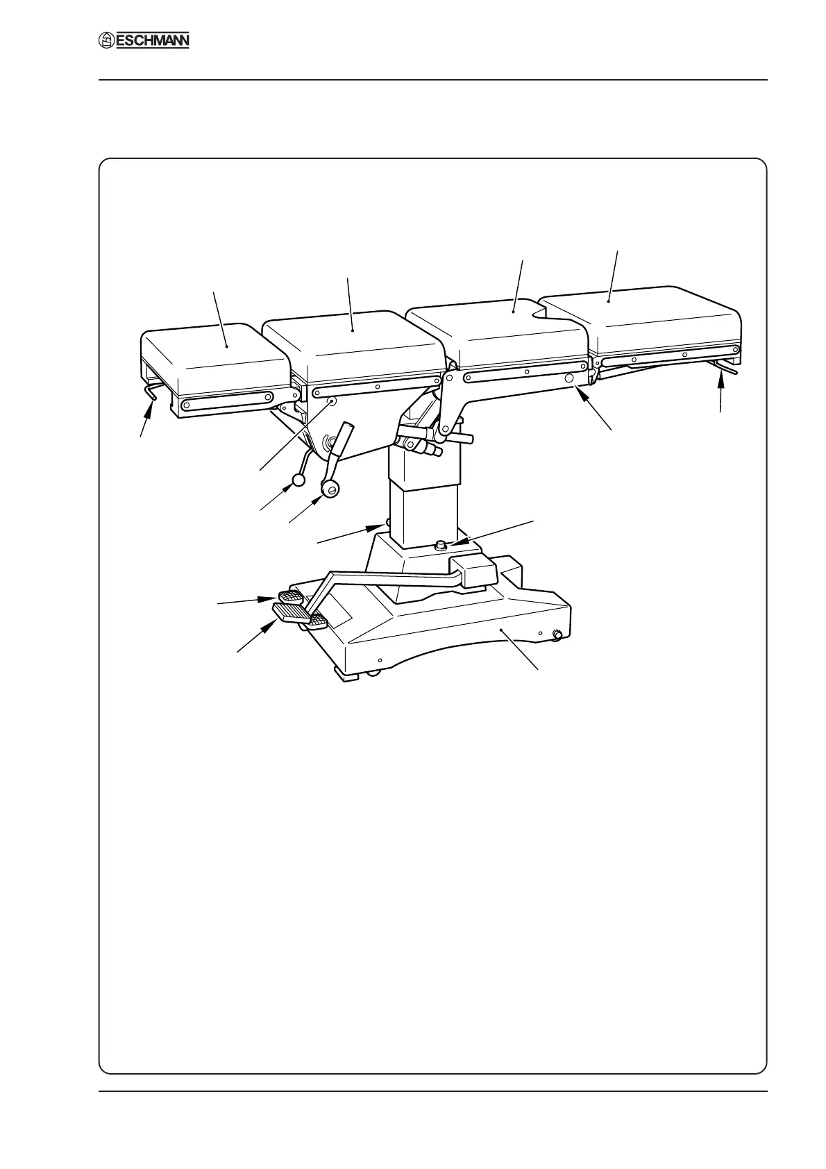
1 Head Section
2 Upper Trunk Section
3 Lower Trunk Section
4 Leg Section
5 Quick-release Bar (Leg Section Angle)
6 Release Button, L.H. (Leg Section)
7 Oil Filler Cap
8 Base
9 Height Control Pedal
10 Base Control Pedal
11 Cylinder Locking Lever
12 Main Control Handle
13 Gear Lever
14 Release Button, R.H. (Head Section)
15 Quick Release Bar (Head Section Angle)
1
2
3
4
5
6
8
9
10
11
13
7
12
14
15
Fig. 3 MR Operation Table : Part identification and controls
4. MAINTENANCE
Part 4