T-SM5f Page 9 of 29
MR & MRS OPERATION TABLES
Part 4
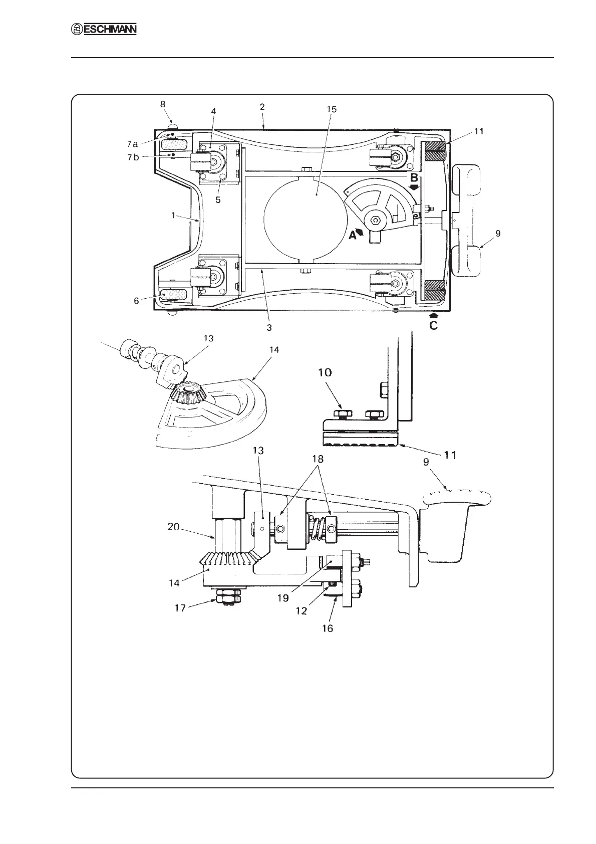
Fig. 5 Base assembly
1. Base casting 8. Wheel spindle 15. Oil sump
2. Base cover 9. Base control pedal 16. Roller
3. Castor frame 10. Brake pad screws 17. Quadrant securing nuts
4. Castor 11. Brake pad 18. Brake shaft collars
5. Castor mounting screw 12. Stop screw 19. Eccentric pin
6. Wheel 13. Pinion 20. Quadrant pillar
7a/b. Grub screws 14. Quadrant
DETAIL A
DETAIL C
DETAIL B
4. MAINTENANCE