MR & MRS OPERATION TABLES
Page 8 of 29 T-SM5f
4. MAINTENANCE
GENERAL
4.1 The information provided in this Service
Manual falls into four categories:
♦ Cleaning, Disinfection, Care and Storage.
♦ Periodic lubrication, checks and adjustments
♦ Fault diagnosis and remedies
♦ Removal and installation of components
CLEANING, DISINFECTION, CARE AND
STORAGE
4.2 For Cleaning, Disinfection, Care and
Storage instructions refer to Section 8 of the
Instructions for Use (Publication T-IM18, also see
section 1.3).
PERIODIC LUBRICATION, CHECKS
AND ADJUSTMENTS
Base Components
4.3 In order to carry out maintenance procedures
to the table base, it is necessary to tilt the table on
its side and expose the underside of the base.
Proceed as follows:
i Remove the head and leg section in the
normal manner (see Instruction for Use,
Publication T-IM18).
ii Raise the table top to its maximum height.
iii Place an anaesthetist’s stool, or similar strong
support, alongside the table.
iv Place the brake pedal in the ‘castor’ position.
v Stand on the same side of the table as the
support but with the pump lever on the
opposite side. Push the table away about
30 cm and then pull it back. This ensures
that all the castors are pointing away from
the operator. Two people on the same side of
the table as the support (one at each end) can
now each place a foot against the base and
lever the table over gently, lowering it onto
the support.
Castors and wheels
4.4. Clean each castor (see Fig. 5) and wheel free
of debris, then lubricate the castor and wheel ball
races with a light machine oil (or WD40 aerosol
lubricant).
Part 4
Brakes and brake mechanism
4.5. Check the action of the brake mechanism
(see Fig. 5) and also check for wear on the brake
pads, broken brake pinion or quadrant teeth, play
in the quadrant taper pins and adjustment between
quadrant, roller and eccentric pin. Check stop
screws for wear. To replace quadrant see section
4.44; to replace quadrant pinion, see section 4.45.
4.6 Fit new brake pads where necessary,
referring to section 4.43.
Hydraulic Cylinder
4.7 Raise the table top to its maximum height,
then depress the height adjustment (hydraulic
pump) pedal fully and check for smoothness and
rate of descent.
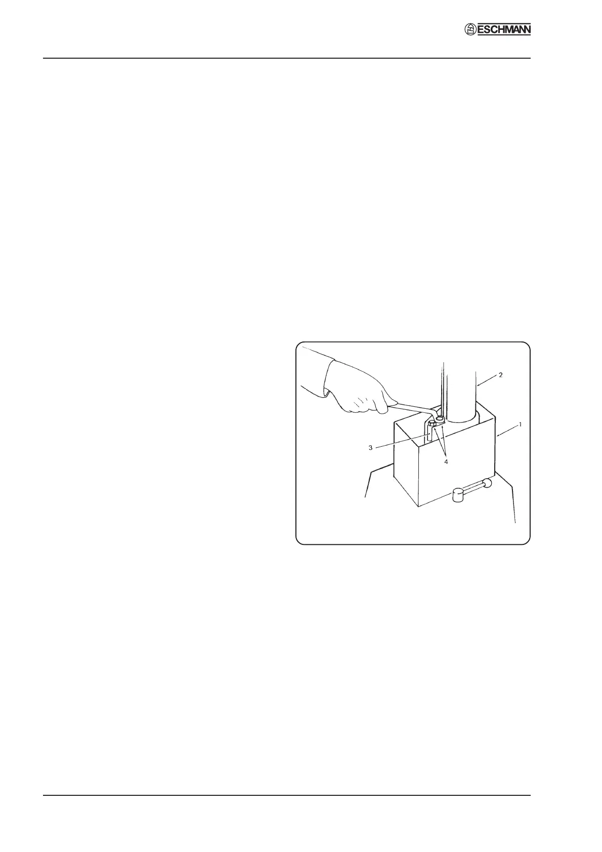
Fig. 4 Ram key adjustment
4.8 Raise the table top to its maximum height
again and release the ram cover securing screws
at the top. Refer to Fig. 4 and lower the 3-section
telescopic cover (1) to expose the ram (2) and ram
key (3).
4.9 Remove the ram key, clean out keyway and
refit key.
4.10 Examine ram surface for rust and, if present,
clean off with fine emery cloth. (Note: Later rams
have a black surface coating do not confuse this
with rust and attempt to remove it). Lubricate
exposed surface of ram. Seal the top of the cylinder
with cloth wound round the ram to prevent damage
if using emery cloth.