User’s Guide Introduction
A.9
Connecting your ESI phone
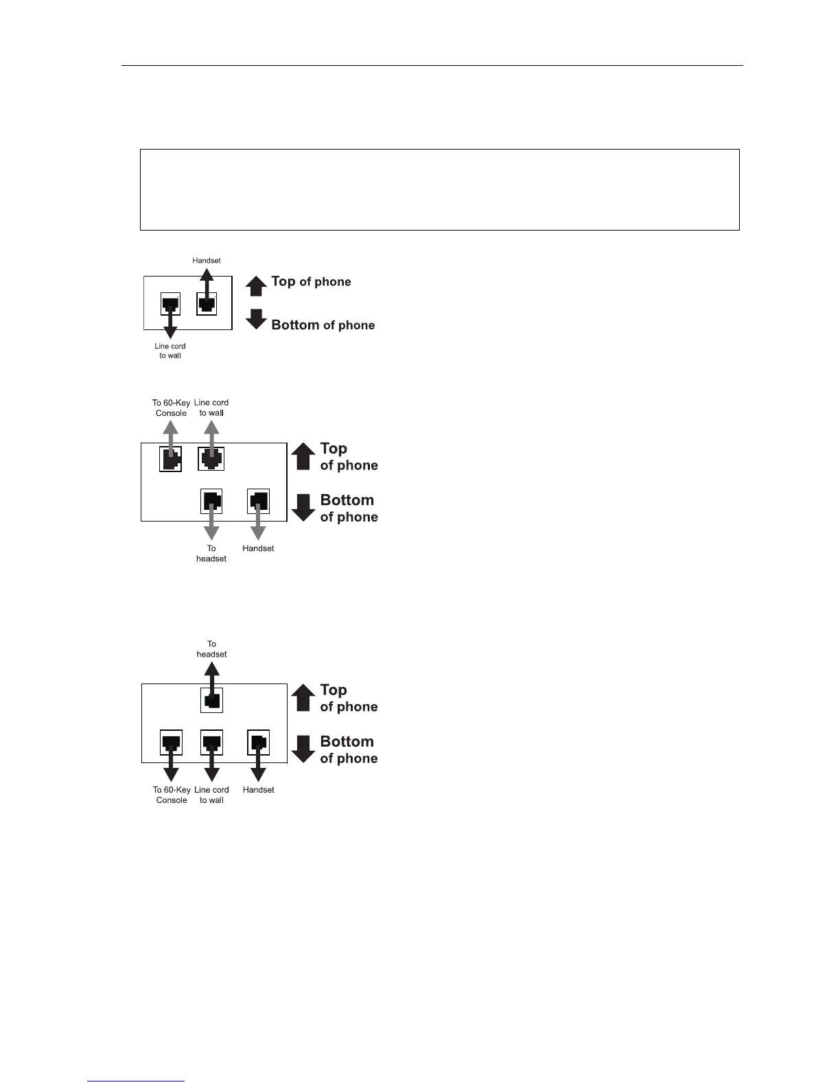
Depending on which ESI phone you have, use the appropriate diagram (below) to connect it. Each diagram
represents the panel on the phone’s underside.
Notes: The “Top of phone” and “Bottom of phone” references in these diagrams show the correct vertical
orientation of the phone — i.e., the part with the display is the top.
When the phone is in the highest upright position, use the wall-mount hook located under the handset to
secure the handset when you’re not using the phone.
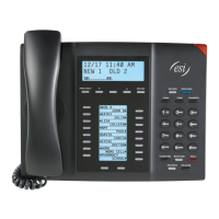
24-Key Feature Phone
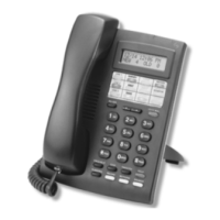
12-Key Feature Phone
(legacy product)
• Connects like a basic phone.
• Handset plugs into right-side jack.
• Line cord plugs into left-side jack.
ESI 60 (digital version)
ESI 40 (digital version)
In addition to how the 24-Key Feature Phone connects to
the handset and line cord, note that each phone in this
group accepts a 60-Key Expansion Console cable
(included with each Console) which uses standard RJ-11
telephone connectors.
48-Key Digital Feature Phone
In addition to how the 24-Key Feature Phone connects
to the handset and line cord, note that this phone
accepts a 60-Key Expansion Console cable (included
with each Console) which uses standard RJ-11
telephone connectors.